Toyota 4Runner: ACC Monitor Malfunction (B2274)
DESCRIPTION
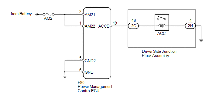
This DTC is stored when there is a problem in the ACC output circuit, which is from the ACC output terminal of the power management control ECU to the ACC relay.
HINT:
When the power management control ECU is replaced with a new one and the cable is connected to the negative (-) battery terminal, the power source mode is reset to on (IG). When the battery is removed and reinstalled, the power source mode that was selected when the battery was removed is restored.
|
DTC Code |
DTC Detection Condition |
Trouble Area |
|---|---|---|
|
B2274 |
The ACC relay actuation circuit inside the power management control ECU or other related circuit is malfunctioning. |
|
WIRING DIAGRAM
CAUTION / NOTICE / HINT
NOTICE:
- When using the Techstream with the engine switch off to troubleshoot: Connect the Techstream to the vehicle and turn a courtesy light switch on and off at 1.5 second intervals until communication between the Techstream and vehicle begins.
- Before performing the inspection, check that there are no problems related to the CAN communication system and LIN communication system.
- Inspect the fuses for circuits related to this system before performing the following inspection procedure.
PROCEDURE
|
1. |
CHECK HARNESS AND CONNECTOR (BATTERY - POWER MANAGEMENT CONTROL ECU) |
.gif)
| NG | .gif) |
REPAIR OR REPLACE HARNESS OR CONNECTOR |
|
.gif)
|
2. |
CHECK HARNESS AND CONNECTOR (POWER MANAGEMENT CONTROL ECU - BODY GROUND) |
| NG | |
REPAIR OR REPLACE HARNESS OR CONNECTOR |
|
|
3. |
INSPECT DRIVER SIDE JUNCTION BLOCK ASSEMBLY (ACC RELAY) |
|
(a) Remove the driver side junction block assembly. |
|
(b) Measure the resistance according to the value(s) in the table below.
Standard Resistance:
|
Tester Connection |
Condition |
Specified Condition |
|---|---|---|
|
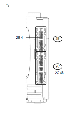
2C-48 - 2B-4 |
20°C (68°F) |
101.25 to 123.75 Ω |
|
*a |
Component without harness connected (Driver Side Junction Block Assembly) |
| NG | |
REPLACE MAIN BODY ECU (DRIVER SIDE JUNCTION BLOCK ASSEMBLY) |
|
|
4. |
CHECK HARNESS AND CONNECTOR (POWER MANAGEMENT CONTROL ECU - DRIVER SIDE JUNCTION BLOCK ASSEMBLY) |
(a) Disconnect the F80 power management control ECU connector.
(b) Disconnect the 2C driver side junction block assembly connector.
(c) Measure the resistance according to the value(s) in the table below.
Standard Resistance:
|
Tester Connection |
Condition |
Specified Condition |
|---|---|---|
|
F80-19 (ACCD) - 2C-48 |
Always |
Below 1 Ω |
|
F80-19 (ACCD) - Body ground |
Always |
10 kΩ or higher |
| NG | |
REPAIR OR REPLACE HARNESS OR CONNECTOR |
|
|
5. |
CHECK HARNESS AND CONNECTOR (DRIVER SIDE JUNCTION BLOCK ASSEMBLY - BODY GROUND) |
| NG | |
REPAIR OR REPLACE HARNESS OR CONNECTOR |
|
|
6. |
CHECK POWER MANAGEMENT CONTROL ECU |
(a) Connect the power management control ECU connector.
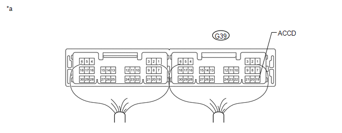 Text in Illustration
|
*a |
Component with harness connected (Power Management Control ECU) |
- |
- |
(b) Measure the voltage according to the value(s) in the table below.
Standard Voltage:
|
Tester Connection |
Switch Condition |
Specified Condition |
|---|---|---|
|
F80-19 (ACCD) - Body ground |
Engine switch off |
Below 1 V |
|
Engine switch on (ACC) |
((Voltage at terminal AM21 or AM22) minus 2.0 V) or higher |
| OK | |
USE SIMULATION METHOD TO CHECK |
| NG | |
REPLACE POWER MANAGEMENT CONTROL ECU |
 Runnable Signal Malfunction (B2286,P0335)
DESCRIPTION
The power management control ECU and ECM are connected by a cable and the CAN
communication lines. These DTCs are stored when the crankshaft position sensor signal
information from th ...
 Vehicle Speed Signal Malfunction (B2282,B2283)
DESCRIPTION
The power management control ECU and the combination meter are connected by a
cable and the CAN communication lines. This DTC is stored when the vehicle speed
signal information from ...
Other materials about Toyota 4Runner:
Reassembly
REASSEMBLY
PROCEDURE
1. INSTALL REAR PROPELLER SHAFT UNIVERSAL JOINT SPIDER BEARING
HINT:
Use the same procedure for all rear propeller shaft universal joint spider bearing.
(a) Apply MP grease to the universal joint spider and new bearings.
...
Installing child restraints
Follow the child restraint system manufacturer’s instructions. Firmly
secure the child restraints using the LATCH anchors or a seat belt.
Attach the top tether strap when installing a child restraint.
The lap/shoulder belt can be used if your child restr ...
0.0079