Toyota 4Runner: ACC Signal Circuit
DESCRIPTION
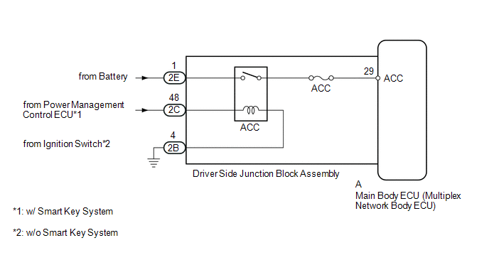
This circuit detects the ignition switch ACC or off condition, and sends it to the main body ECU.
WIRING DIAGRAM
CAUTION / NOTICE / HINT
NOTICE:
Inspect the fuses for circuits related to this system before performing the following inspection procedure.
PROCEDURE
|
1. |
READ VALUE USING TECHSTREAM (IGNITION SWITCH) |
(a) Using the Techstream, read the Data List (See page
.gif) ).
).
Main Body
|
Tester Display |
Measurement Item/Range |
Normal Condition |
Diagnostic Note |
|---|---|---|---|
|
ACC SW |
Ignition switch ACC signal / ON or OFF |
ON: Ignition switch ACC OFF: Ignition switch off |
- |
OK:
Normal conditions listed above are displayed.
| OK | .gif) |
PROCEED TO NEXT SUSPECTED AREA SHOWN IN PROBLEM SYMPTOMS TABLE |
|
.gif)
|
2. |
CHECK HARNESS AND CONNECTOR (BATTERY - MAIN BODY ECU) |
|
(a) Remove the main body ECU (See page
|
|
(b) Measure the voltage according to the value(s) in the table below.
Standard Voltage:
|
Tester Connection |
Switch Condition |
Specified Condition |
|---|---|---|
|
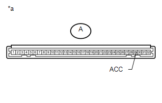
A-29 (ACC) - Body ground |
Ignition switch ACC |
11 to 14 V |
|
*a |
Front view of wire harness connector (to Main Body ECU) |
| OK | |
REPLACE MAIN BODY ECU (MULTIPLEX NETWORK BODY ECU) |
| NG | |
REPAIR OR REPLACE HARNESS OR CONNECTOR |
 Data List / Active Test
DATA LIST / ACTIVE TEST
1. DATA LIST
HINT:
Using the Techstream to read the Data List allows the values or states of switches,
sensors, actuators and other items to be read without removing any p ...
 IG Signal Circuit
DESCRIPTION
This circuit detects the ignition switch ON or off condition, and sends it to
the main body ECU.
WIRING DIAGRAM
CAUTION / NOTICE / HINT
NOTICE:
Inspect the fuses for circuits rela ...
Other materials about Toyota 4Runner:
Illumination for Panel Switch does not Come on with Tail Switch ON
CAUTION / NOTICE / HINT
NOTICE:
After replacing the navigation receiver assembly of vehicles subscribed to pay-type
satellite radio broadcasts, registration of the XM radio ID is necessary.
PROCEDURE
1.
CHECK VEHICLE SIGNAL (OPERAT ...
Back Power Window Switch
Components
COMPONENTS
ILLUSTRATION
Removal
REMOVAL
PROCEDURE
1. REMOVE SHIFT LEVER KNOB SUB-ASSEMBLY
2. REMOVE SHIFT LEVER KNOB SUB-ASSEMBLY (for VF2A)
3. REMOVE UPPER CONSOLE PANEL SUB-ASSEMBLY
4. REMOVE BACK DOOR POWER WINDOW REGULATO ...
0.009