Toyota 4Runner: Adjustment
ADJUSTMENT
PROCEDURE
1. CHECK BRAKE PEDAL HEIGHT
|
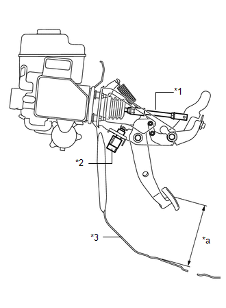
(a) Check the brake pedal height. Pedal height from Floor panel: 158.8 to 168.8 mm (6.25 to 6.46 in.) Text in Illustration
NOTICE: Do not adjust the pedal height. Doing so by changing the push rod length will structurally change the pedal ratio. If the pedal height is incorrect, adjust the rod operating adapter length. |
|
|
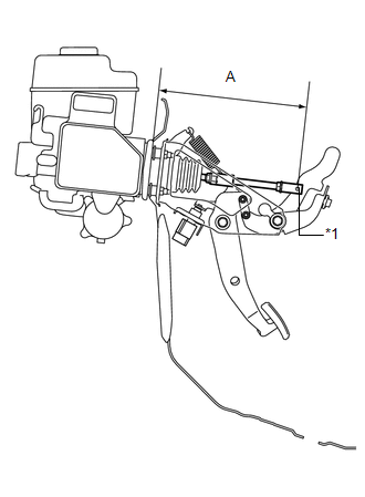
(b) Adjust the rod operating adapter length. (1) Remove the clip and clevis pin. (2) Loosen the clevis lock nut. Text in Illustration
(3) Adjust the rod operating adapter length by turning the pedal push rod clevis. Rod operating adapter length "A": 236.3 to 237.3 mm (9.30 to 9.34 in.) (4) Tighten the clevis lock nut. Torque: 26 N·m {260 kgf·cm, 19 ft·lbf} (5) Install the clip and clevis pin. If the pedal height is incorrect even if the rod operating adapter is adjusted, check that there is no damage to the brake pedal, brake pedal lever, brake pedal bracket or floor panel.
|
|
2. CHECK AND ADJUST STOP LIGHT SWITCH ASSEMBLY
HINT:
If the pedal height is incorrect, check and adjust the stop light switch clearance.
(a) Disconnect the stop light switch assembly connector from the stop light switch assembly.
(b) Turn the stop light switch assembly counterclockwise and remove the stop light switch assembly.
|
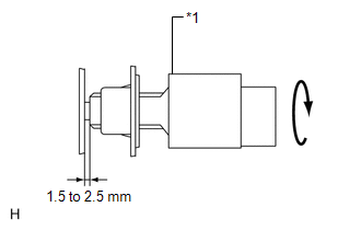
(c) Insert the stop light switch assembly until the body hits the cushion. Text in Illustration
NOTICE: When inserting the stop light switch assembly, support the pedal from behind so that the pedal is not pushed in. |
|
(d) Make a quarter turn clockwise to install the stop light switch assembly.
NOTICE:
The turning torque for installing the stop light switch should be 1.5 N*m (15 kgf*cm, 13 in.*lbf) or less.
HINT:
Due to the inverse screw structure, if the stop light switch assembly is turned clockwise, the stop light switch assembly moves in the direction to be pulled out.
(e) Connect the stop light switch connector to the stop light switch assembly.
(f) Check the protrusion of the rod.
Protrusion of the rod:
1.5 to 2.5 mm (0.0591 to 0.0984 in.)
(g) Install the clevis pin and clip.
(h) After adjusting the pedal height, check the pedal free play.
3. CHECK PEDAL FREE PLAY
|
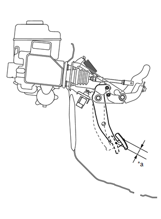
(a) Push in the pedal until the resistance is felt. Measure the distance. Text in Illustration
Pedal free play: 1 to 6 mm (0.0394 to 0.236 in.) HINT: Check the brake pedal free play at the same location as that used when checking the brake pedal height. |
|
4. CHECK PEDAL RESERVE DISTANCE
|
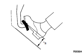
(a) Release the parking brake pedal. With the engine running, depress the pedal and measure the pedal reserve distance. Text in Illustration
Pedal reserve distance from floor panel at 490 N (50 kgf, 110.2 lbf): More than 92 mm (3.62 in.) If incorrect, troubleshoot the brake system. HINT: Insert a ruler into the slit to measure the pedal reserve distance. |
|
 Removal
REMOVAL
PROCEDURE
1. DISCONNECT CABLE FROM NEGATIVE BATTERY TERMINAL
CAUTION:
Wait at least 90 seconds after disconnecting the cable from the negative (-)
battery terminal to disable the SRS sys ...
 Reassembly
REASSEMBLY
PROCEDURE
1. INSTALL STOP LIGHT SWITCH MOUNTING ADJUSTER
(a) Install a new stop light switch mounting adjuster to the brake pedal support.
2. INSTALL BRAKE PEDAL PAD
(a) Install the br ...
Other materials about Toyota 4Runner:
Rear Power Window LH does not Operate with Rear Power Window Switch LH
DESCRIPTION
If the manual up/down function does not operate, there may be a malfunction
in the rear power window regulator switch, rear power window regulator motor,
harness or connector.
WIRING DIAGRAM
CAUTION / NOTICE / HINT
NOTICE ...
Diagnostic Trouble Code Chart
DIAGNOSTIC TROUBLE CODE CHART
HINT:
If a trouble code is output during the DTC check, inspect the trouble areas listed
for that code. For details of the code, refer to the "See page" below.
Power Window Control System
DTC Code
...
0.0064