Toyota 4Runner: Air Conditioning Control Panel does not Operate
DESCRIPTION
When a switch of the air conditioning control assembly is operated, the air conditioning control assembly uses LIN communication to communicate with the air conditioning amplifier. If a switch of the air conditioning control assembly does not operate properly, a problem with the LIN communication between the air conditioning control assembly and air conditioning amplifier may be causing the malfunction.
WIRING DIAGRAM
PROCEDURE
|
1. |
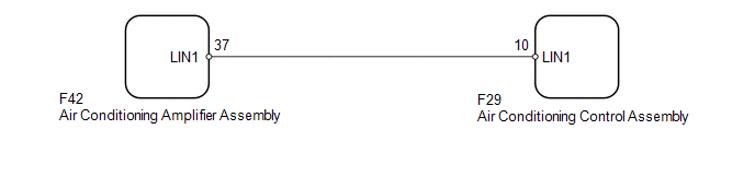
CHECK HARNESS AND CONNECTOR (AIR CONDITIONING AMPLIFIER - AIR CONDITIONING CONTROL) |
(a) Disconnect the F42 air conditioning amplifier assembly connector.
(b) Disconnect the F29 air conditioning control assembly connector.
(c) Measure the resistance according to the value(s) in the table below.
Standard Resistance:
|
Tester Connection |
Condition |
Specified Condition |
|---|---|---|
|
F42-37 (LIN1) - F29-10 (LIN1) |
Always |
Below 1 Ω |
|
F42-37 (LIN1) or F29-10 (LIN1) - Body ground |
Always |
10 kΩ or higher |
|
Result |
Proceed to |
|---|---|
|
OK (for Automatic Air Conditioning System) |
A |
|
OK (for Manual Air Conditioning System) |
B |
|
NG |
C |
| A | .gif) |
Go to AIR CONDITIONING SYSTEM (for Automatic Air Conditioning System) |
| B | |
Go to AIR CONDITIONING SYSTEM |
| C | |
REPAIR OR REPLACE HARNESS OR CONNECTOR |
 Sliding Roof ECU Communication Stop (B1273)
DESCRIPTION
This DTC is stored when LIN communication between the sliding roof ECU (sliding
roof drive gear sub-assembly) and main body ECU (multiplex network body ECU) stops
for 10 seconds or mo ...

Other materials about Toyota 4Runner:
Power outlets (120 V AC)
The power outlet can be used for electrical appliances.
Main switch
To use the power outlet, turn on the main switch.
The power supply starts a few seconds after the main switch is pressed.
Power outlet socket (in the console box)
Power outlet socket ...
Installation
INSTALLATION
CAUTION / NOTICE / HINT
HINT:
Use the same procedure for the RH and LH sides.
The procedure listed below is for the LH side.
PROCEDURE
1. INSTALL FRONT DISC
(a) Align the matchmarks and install the front disc.
HINT:
When ...
0.0079