Toyota 4Runner: All Doors LOCK/UNLOCK Functions do not Operate Via Master Switch, Driver Side Door Key Cylinder
DESCRIPTION
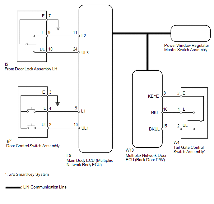
The main body ECU (multiplex network body ECU) receives switch signals from the multiplex network master switch, and key-linked switch signals from the front door lock. The main body ECU (multiplex network body ECU) activates the door lock motor on each door according to these signals.
WIRING DIAGRAM
CAUTION / NOTICE / HINT
NOTICE:
Inspect the fuses for circuits related to this system before performing the following inspection procedure.
HINT:
Since the power door lock control system has functions that use LIN communication, first confirm that there is no malfunction in the communication system by inspecting the LIN communication functions in accordance with the "How to Proceed with Troubleshooting" procedures. Then, conduct the following inspection procedure.
PROCEDURE
|
1. |
CHECK DOOR LOCK OPERATION |
(a) Check the door lock operation.
Result|
Result |
Proceed to |
|---|---|
|
No doors can be locked using multiplex network master switch |
A |
|
No doors can be locked using door control switch |
B |
|
No doors can be locked using key-linked switch |
C |
|
No doors can be locked using tail gate control switch* |
D |
- *: w/o Smart Key System
| A | .gif) |
REPLACE MULTIPLEX NETWORK MASTER SWITCH ASSEMBLY |
| C | |
GO TO STEP 5 |
| D | |
GO TO STEP 8 |
|
.gif)
|
2. |
READ VALUE USING TECHSTREAM (DOOR CONTROL SWITCH) |
(a) Use the Data List to check if the door control switch is functioning properly
(See page .gif) ).
).
Main Body
|
Tester Display |
Measurement Item/Range |
Normal Condition |
Diagnostic Note |
|---|---|---|---|
|
Door Lock SW-Lock |
Door control switch lock signal / ON or OFF |
ON: Lock side of door control switch pushed OFF: Lock side of door control switch not pushed |
- |
|
Door Lock SW-Unlock |
Door control switch unlock signal / ON or OFF |
ON: Unlock side of door control switch pushed OFF: Unlock side of door control switch not pushed |
- |
OK:
On tester screen, each item changes between ON and OFF according to above chart.
| OK | |
REPLACE MAIN BODY ECU (MULTIPLEX NETWORK BODY ECU) |
|
|
3. |
INSPECT DOOR CONTROL SWITCH ASSEMBLY |
|
(a) Remove the door control switch (See page
|
|
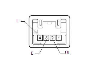
(b) Measure the resistance according to the value(s) in the table below.
Standard Resistance:
|
Tester Connection |
Condition |
Specified Condition |
|---|---|---|
|
4 (L) - 3 (E) |
Lock |
Below 1 Ω |
|
4 (L) - 3 (E) |
Off |
10 kΩ or higher |
|
2 (UL) - 3 (E) |
Unlock |
Below 1 Ω |
|
2 (UL) - 3 (E) |
Off |
10 kΩ or higher |
| NG | |
REPLACE DOOR CONTROL SWITCH ASSEMBLY |
|
|
4. |
CHECK HARNESS AND CONNECTOR (DOOR CONTROL SWITCH ASSEMBLY - MAIN BODY ECU) |
(a) Disconnect the g2 door control switch connector.
(b) Disconnect the F9 main body ECU connector.
(c) Measure the resistance according to the value(s) in the table below.
Standard Resistance:
|
Tester Connection |
Condition |
Specified Condition |
|---|---|---|
|
g2-2 (UL) - F9-10 (UL1) |
Always |
Below 1 Ω |
|
g2-4 (L) - F9-9 (L1) |
Always |
Below 1 Ω |
|
g2-3 (E) - Body ground |
Always |
Below 1 Ω |
|
g2-2 (UL) - Body ground |
Always |
10 kΩ or higher |
|
g2-4 (L) - Body ground |
Always |
10 kΩ or higher |
| OK | |
REPLACE MAIN BODY ECU (MULTIPLEX NETWORK BODY ECU) |
| NG | |
REPAIR OR REPLACE HARNESS OR CONNECTOR |
|
5. |
READ VALUE USING TECHSTREAM (KEY-LINKED SWITCH) |
(a) Use the Data List to check if the door key-linked switch is functioning properly
(See page ).
Main Body
|
Tester Display |
Measurement Item/Range |
Normal Condition |
Diagnostic Note |
|---|---|---|---|
|
Door Key SW-Lock |
Driver side door key-linked switch lock signal / ON or OFF |
ON: Driver side door key cylinder turned to lock position OFF: Driver side door key cylinder not turned to lock position |
- |
|
D Door Key SW-UL |
Driver side door key-linked switch unlock signal / ON or OFF |
ON: Driver side door key cylinder turned to unlock position OFF: Driver side door key cylinder not turned to unlock position |
- |
OK:
On tester screen, each item changes between ON and OFF according to above chart.
| OK | |
REPLACE MAIN BODY ECU (MULTIPLEX NETWORK BODY ECU) |
|
|
6. |
INSPECT FRONT DOOR LOCK ASSEMBLY LH (KEY-LINKED SWITCH) |
(a) Remove the front door lock LH (See page
).
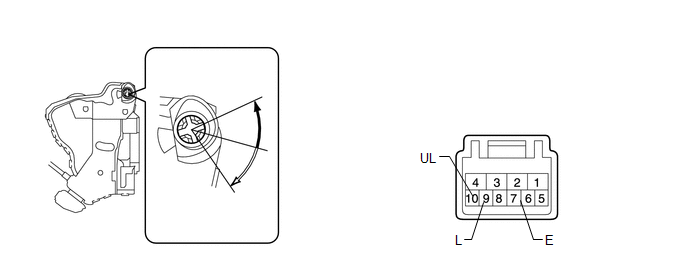 Text in Illustration
.png) |
Lock |
.png) |
Unlock |
(b) Measure the resistance according to the value(s) in the table below.
Standard Resistance:
|
Tester Connection |
Condition |
Specified Condition |
|---|---|---|
|
9 (L) - 7 (E) |
Lock |
Below 1 Ω |
|
9 (L) - 7 (E) |
Off |
10 kΩ or higher |
|
10 (UL) - 7 (E) |
Unlock |
Below 1 Ω |
|
10 (UL) - 7 (E) |
Off |
10 kΩ or higher |
| NG | |
REPLACE FRONT DOOR LOCK ASSEMBLY LH |
|
|
7. |
CHECK HARNESS AND CONNECTOR (FRONT DOOR LOCK ASSEMBLY LH - MAIN BODY ECU AND BODY GROUND) |
(a) Disconnect the I5 door lock connector.
(b) Remove the main body ECU connector. (See page
)
(c) Measure the resistance according to the value(s) in the table below.
Standard Resistance:
|
Tester Connection |
Condition |
Specified Condition |
|---|---|---|
|
I5-10 (UL) - F9-24 (UL3) |
Always |
Below 1 Ω |
|
I5-9 (L) - F9-11 (L2) |
Always |
Below 1 Ω |
|
I5-7 (E) - Body ground |
Always |
Below 1 Ω |
|
I5-10 (UL) - Body ground |
Always |
10 kΩ or higher |
|
I5-9 (L) - Body ground |
Always |
10 kΩ or higher |
| OK | |
REPLACE MAIN BODY ECU (MULTIPLEX NETWORK BODY ECU) |
| NG | |
REPAIR OR REPLACE HARNESS OR CONNECTOR |
|
8. |
READ VALUE USING TECHSTREAM (TAIL GATE CONTROL SWITCH) |
(a) Use the Data List to check if the tail gate control switch and back door
are functioning properly (See page ).
Back Door P/W
|
Tester Display |
Measurement Item/Range |
Normal Condition |
Diagnostic Note |
|---|---|---|---|
|
Key Switch Operation Locked |
Tail gate control switch signal / ON or OFF |
ON: Back door key cylinder turned to lock position OFF: Back door key cylinder not turned |
- |
|
Key Switch Operation Unlocked |
Tail gate control switch signal / ON or OFF |
ON: Back door key cylinder turned to unlock position OFF: Back door key cylinder not turned |
- |
|
Back Door Courtesy Switch |
Back door courtesy switch signal / ON or OFF |
ON: Back door open OFF: Back door closed |
- |
|
Result |
Proceed to |
|---|---|
|
OK |
A |
|
NG (Key Switch Operation Locked or Key Switch Operation Unlocked) |
B |
|
NG (Back Door Courtesy Switch) |
C |
| A | |
REPLACE MULTIPLEX NETWORK DOOR ECU (BACK DOOR P/W) |
| C | |
GO TO "Only Back Door cannot be Opened" |
|
|
9. |
INSPECT TAIL GATE CONTROL SWITCH ASSEMBLY |
(a) Remove the tail gate control switch (See page
).
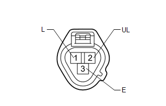
(b) Measure the resistance according to the value(s) in the table below.
Standard Resistance:
|
Tester Connection |
Condition |
Specified Condition |
|---|---|---|
|
1 (L) - 3 (E) |
Lock position |
Below 1 Ω |
|
1 (L) - 3 (E) |
Unlock position |
10 kΩ or higher |
|
2 (UL) - 3 (E) |
Unlock position |
Below 1 Ω |
|
2 (UL) - 3 (E) |
Lock position |
10 kΩ or higher |
| NG | |
REPLACE TAIL GATE CONTROL SWITCH ASSEMBLY |
|
|
10. |
CHECK HARNESS AND CONNECTOR (TAIL GATE CONTROL SWITCH ASSEMBLY - MULTIPLEX NETWORK DOOR ECU) |
(a) Disconnect the W4 tail gate control switch connector.
(b) Disconnect the W10 multiplex network door ECU connector.
(c) Measure the resistance according to the value(s) in the table below.
Standard Resistance:
|
Tester Connection |
Condition |
Specified Condition |
|---|---|---|
|
W4-1 (L) - W10-16 (BKL) |
Always |
Below 1 Ω |
|
W4-2 (UL) - W10-15 (BKUL) |
Always |
Below 1 Ω |
|
W4-3 (E) - W10-8 (KEYE) |
Always |
Below 1 Ω |
|
W4-1 (L) - Body ground |
Always |
10 kΩ or higher |
|
W4-2 (UL) - Body ground |
Always |
10 kΩ or higher |
| OK | |
REPLACE MULTIPLEX NETWORK DOOR ECU (BACK DOOR P/W) |
| NG | |
REPAIR OR REPLACE HARNESS OR CONNECTOR |
 Dtc Check / Clear
DTC CHECK / CLEAR
1. CHECK DTC
(a) Connect the Techstream to the DLC3.
(b) Turn the ignition switch to ON.
(c) Turn the Techstream on.
(d) Enter the following menus: Body Electrical / Trouble Cod ...
 Data List / Active Test
DATA LIST / ACTIVE TEST
1. DATA LIST
HINT:
Using the Techstream to read the Data List allows the values or states of switches,
sensors, actuators and other items to be read without removing any p ...
Other materials about Toyota 4Runner:
How To Proceed With Troubleshooting
CAUTION / NOTICE / HINT
HINT:
Use these procedures to troubleshoot the theft deterrent system.
*: Use the Techstream.
The troubleshooting procedures for the theft deterrent system are based
on the premise that the door lock control sys ...
Inspection
INSPECTION
PROCEDURE
1. INSPECT VANE PUMP SHAFT AND BUSH IN VANE PUMP FRONT HOUSING
(a) Using a micrometer, measure the outer diameter of the vane pump shaft.
Text in Illustration
*a
Outer Diameter
...
0.0096