Toyota 4Runner: Automatic Running Board Switch
Components
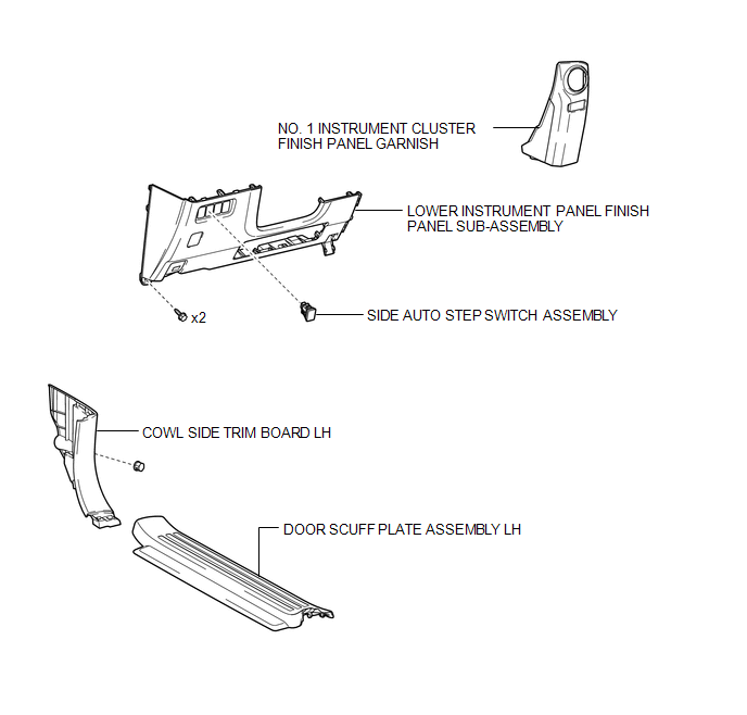
COMPONENTS
ILLUSTRATION
Removal
REMOVAL
PROCEDURE
1. REMOVE DOOR SCUFF PLATE ASSEMBLY LH
.gif)
2. REMOVE COWL SIDE TRIM BOARD LH
3. REMOVE NO. 1 INSTRUMENT CLUSTER FINISH PANEL GARNISH
4. REMOVE LOWER INSTRUMENT PANEL FINISH PANEL SUB-ASSEMBLY
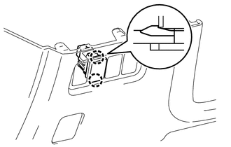
5. REMOVE SIDE AUTO STEP SWITCH ASSEMBLY
|
(a) Disengage the 2 claws and remove the side auto step switch assembly. |
|
Inspection
INSPECTION
PROCEDURE
1. INSPECT SIDE AUTO STEP SWITCH ASSEMBLY
|
(a) Measure the resistance according to the value(s) in the table below. Standard Resistance:
|
|
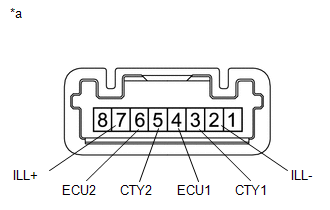
(b) Apply battery voltage to the connector and check the LED illumination.
OK:
|
Measurement Condition |
Specified Condition |
|---|---|
|
Battery positive (+) → Terminal 7 (ILL+) Battery negative (-) → Terminal 2 (ILL-) |
LED illuminates |
Installation
INSTALLATION
CAUTION / NOTICE / HINT
HINT:
A bolt without a torque specification is shown in the standard bolt chart (See
page .gif) ).
).
PROCEDURE
1. INSTALL SIDE AUTO STEP SWITCH ASSEMBLY
(a) Engage the 2 claws and install the side auto step switch assembly.
2. INSTALL LOWER INSTRUMENT PANEL FINISH PANEL SUB-ASSEMBLY
3. INSTALL NO. 1 INSTRUMENT CLUSTER FINISH PANEL GARNISH
4. INSTALL COWL SIDE TRIM BOARD LH
5. INSTALL DOOR SCUFF PLATE ASSEMBLY LH
 Removal
REMOVAL
PROCEDURE
1. DISCONNECT CABLE FROM NEGATIVE BATTERY TERMINAL
CAUTION:
Wait at least 90 seconds after disconnecting the cable from the negative (-)
battery terminal to disable the SRS sys ...

Other materials about Toyota 4Runner:
Rear Brake Flexible Hose
Components
COMPONENTS
ILLUSTRATION
ILLUSTRATION
Removal
REMOVAL
CAUTION / NOTICE / HINT
HINT:
Use the same procedure for the RH and LH sides.
The procedure listed below is for the LH side.
PROCEDURE
1. REMOVE REAR WHEEL
2. ...
If you think something is wrong
If you notice any of the following symptoms, your vehicle probably needs
adjustment or repair. Contact your Toyota dealer as soon as possible.
Visible symptoms
• Fluid leaks under the vehicle (Water dripping from the air
conditioning after use is norm ...
0.0261