Toyota 4Runner: Back Camera Disconnected (C1622)
DESCRIPTION
This DTC is stored if the navigation receiver assembly judges that the signals or signal lines between the navigation receiver assembly, and the rear television camera assembly are not normal as a result of its self check.
|
DTC No. |
Detection Item |
DTC Detection Condition |
Trouble Area |
|---|---|---|---|
|
C1622 |
Back Camera Disconnected |
Open or short in the rear television camera assembly signal circuit |
|
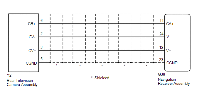
WIRING DIAGRAM
PROCEDURE
|
1. |
CHECK HARNESS AND CONNECTOR (NAVIGATION RECEIVER ASSEMBLY - REAR TELEVISION CAMERA ASSEMBLY) |
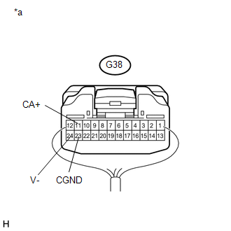
(a) Disconnect the G38 navigation receiver assembly connector.
(b) Disconnect the Y2 rear television camera assembly connector.
(c) Measure the resistance according to the value(s) in the table below.
Standard Resistance:
|
Tester Connection |
Condition |
Specified Condition |
|---|---|---|
|
G38-11 (CA+) - Y2-6 (CB+) |
Always |
Below 1 Ω |
|
G38-12 (V+) - Y2-3 (CV+) |
Always |
Below 1 Ω |
|
G38-23 (CGND) - Y2-5 (CGND) |
Always |
Below 1 Ω |
|
G38-24 (V-) - Y2-2 (CV-) |
Always |
Below 1 Ω |
|
G38-11 (CA+) - Body ground |
Always |
10 kΩ or higher |
|
G38-12 (V+) - Body ground |
Always |
10 kΩ or higher |
|
G38-23 (CGND) - Body ground |
Always |
10 kΩ or higher |
|
G38-24 (V-) - Body ground |
Always |
10 kΩ or higher |
| NG | .gif) |
REPAIR OR REPLACE HARNESS OR CONNECTOR |
|
.gif)
|
2. |
INSPECT NAVIGATION RECEIVER ASSEMBLY |
|
(a) Reconnect the G38 navigation receiver assembly connector. |
|
(b) Measure the resistance according to the value(s) in the table below.
Standard Resistance:
|
Tester Connection |
Condition |
Specified Condition |
|---|---|---|
|
G38-23 (CGND) - Body ground |
Always |
Below 1 Ω |
|
G38-24 (V-) - Body ground |
Always |
Below 1 Ω |
(c) Measure the voltage according to the value(s) in the table below.
Standard Voltage:
|
Tester Connection |
Condition |
Specified Condition |
|---|---|---|
|
G38-11 (CA+) - G38-23 (CGND) |
Ignition switch ACC |
5.5 to 7.05 V |
| NG | |
REPLACE NAVIGATION RECEIVER ASSEMBLY |
|
|
3. |
INSPECT REAR TELEVISION CAMERA ASSEMBLY |
(a) Reconnect the Y2 rear television camera assembly connector.
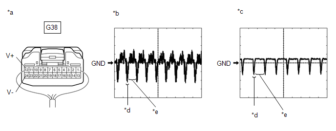
(b) Check the waveform of the rear television camera assembly using an oscilloscope.
HINT:
A waterproof connector is used for the rear television camera assembly. Therefore, inspect the waveform at the navigation receiver assembly with the connector connected.
|
*a |
Component with harness connected (Navigation Receiver Assembly) |
*b |
Waveform 1 (under normal conditions) |
|
*c |
Waveform 2 (camera lens is covered, blacking out the screen) |
*d |
Synchronized Signal |
|
*e |
Video Waveform |
- |
- |
OK:
Waveform is as shown in the illustration.
|
Item |
Content |
|---|---|
|
Terminal No. (Symbol) |
G38-12 (V+) - G38-24 (V-) |
|
Tool Setting |
200 mV/DIV., 50 μsec./DIV. |
|
Condition |
Ignition switch ON, shift lever in R |
HINT:
The video waveform changes according to the image sent by the rear television camera assembly.
| OK | |
REPLACE NAVIGATION RECEIVER ASSEMBLY |
| NG | |
REPLACE REAR TELEVISION CAMERA ASSEMBLY |
 Diagnostic Trouble Code Chart
DIAGNOSTIC TROUBLE CODE CHART
Rear View Monitor System
DTC No.
Detection Item
Link
C1622
Back Camera Disconnected
...
 Display Signal Circuit between Navigation Receiver Assembly and Television Camera
Assembly
Display Signal Circuit between Navigation Receiver Assembly and Television Camera
Assembly
DESCRIPTION
This is the display signal circuit between the navigation receiver assembly and
the television camera assembly.
WIRING DIAGRAM
PROCEDURE
1.
CHECK HARNESS AND ...
Other materials about Toyota 4Runner:
Components
COMPONENTS
ILLUSTRATION
ILLUSTRATION
ILLUSTRATION
ILLUSTRATION
ILLUSTRATION
...
System Description
SYSTEM DESCRIPTION
1. DESCRIPTION
(a) System description
In the KDSS (Kinetic Dynamic Suspension System), a cylinder is installed to each
of the front and rear stabilizer bars. The front and rear cylinder upper chambers
and the front and rear lower cham ...
0.0271