Toyota 4Runner: Back Door Opener Switch
Components
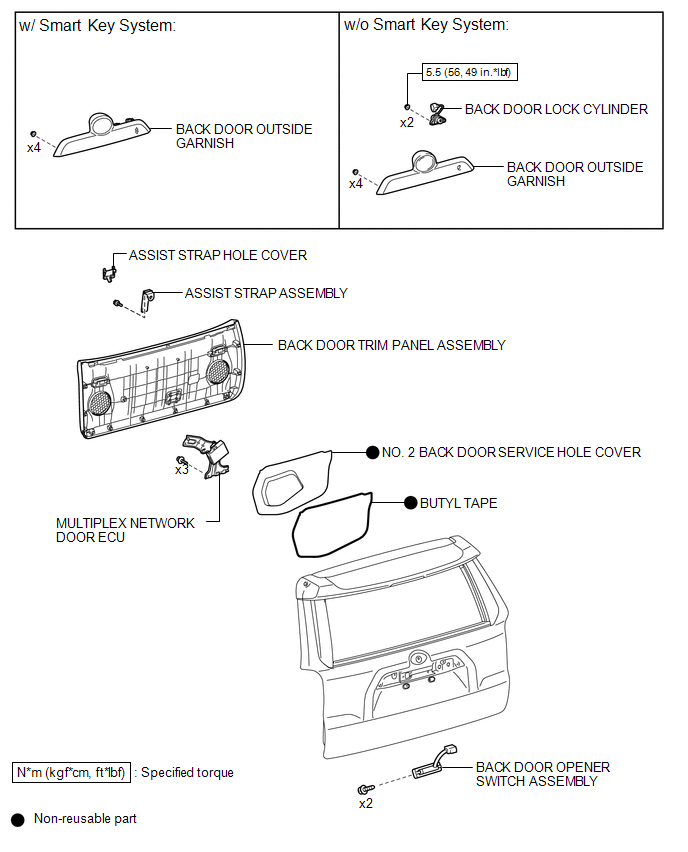
COMPONENTS
ILLUSTRATION
Disassembly
DISASSEMBLY
PROCEDURE
1. REMOVE ASSIST STRAP HOLE COVER
.gif)
2. REMOVE ASSIST STRAP ASSEMBLY
3. REMOVE BACK DOOR TRIM PANEL ASSEMBLY
4. REMOVE MULTIPLEX NETWORK DOOR ECU
5. REMOVE NO. 2 BACK DOOR SERVICE HOLE COVER
6. REMOVE OUTER BACK DOOR GLASS WEATHERSTRIP ASSEMBLY
7. REMOVE BACK DOOR LOCK CYLINDER (w/o Smart Key System)
8. REMOVE BACK DOOR OUTSIDE GARNISH
9. REMOVE BACK DOOR OPENER SWITCH ASSEMBLY
|
(a) Disconnect the connector. |
|
.png)
(b) Detach the guide.
(c) Remove the 2 screws and back door opener switch assembly.
Inspection
INSPECTION
PROCEDURE
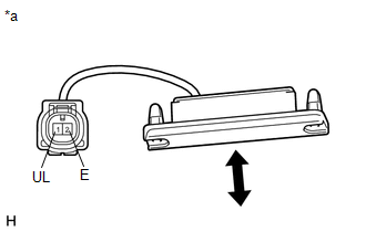
1. INSPECT BACK DOOR OPENER SWITCH ASSEMBLY
(a) Check the operation of the opener switch.
|
(1) Measure the resistance according to the value(s) in the table below. Standard Resistance:
If the result is not specified, replace the back door opener switch assembly. |
|
Reassembly
REASSEMBLY
PROCEDURE
1. INSTALL BACK DOOR OPENER SWITCH ASSEMBLY
|
(a) Install the back door opener switch assembly with the 2 screws. |
|
.png)
(b) Attach the guide and connect the connector.
2. INSTALL BACK DOOR GARNISH OUTSIDE
.gif)
3. INSTALL BACK DOOR LOCK CYLINDER (w/o Smart Key System)
4. INSTALL NO. 2 BACK DOOR SERVICE HOLE COVER
5. INSTALL MULTIPLEX NETWORK DOOR ECU
6. INSTALL BACK DOOR TRIM PANEL ASSEMBLY
7. INSTALL ASSIST STRAP ASSEMBLY
8. INSTALL ASSIST STRAP HOLE COVER
 Reassembly
REASSEMBLY
PROCEDURE
1. INSTALL BACK DOOR UPPER DAMPER STAY BRACKET LH
2. INSTALL BACK DOOR UPPER DAMPER STAY BRACKET RH
HINT:
Use the same procedure as for the LH side.
3. INSTALL BACK DOOR ...
 Back Door Support
Components
COMPONENTS
ILLUSTRATION
Removal
REMOVAL
PROCEDURE
1. REMOVE BACK DOOR DAMPER STAY SUB-ASSEMBLY LH
NOTICE:
Avoid touching the piston rod as much as possible to prevent ...
Other materials about Toyota 4Runner:
Hood
Release the lock from the inside of the vehicle to open the hood.
Pull the hood release lever.
The hood will pop up slightly.
Push the auxiliary catch lever to the left and lift the hood.
CAUTION
Pre-driving check
Check that the hood is fully closed ...
Components
COMPONENTS
ILLUSTRATION
ILLUSTRATION
ILLUSTRATION
ILLUSTRATION
ILLUSTRATION
...
0.0077