Toyota 4Runner: Bleeding
BLEEDING
PROCEDURE
1. BLEED AIR FROM SUSPENSION FLUID
CAUTION:
- Be sure to check the pipe connections and whether or not any hydraulic circuit parts are damaged before performing work as the hydraulic circuits become highly pressurized during air bleeding.
- The pipes become highly pressurized when bleeding air. If a fluid leak is discovered, immediately release the pressure and repair the fluid leak as there is danger involved.
HINT:
When bleeding air, approximately 6 liters of new fluid is needed.
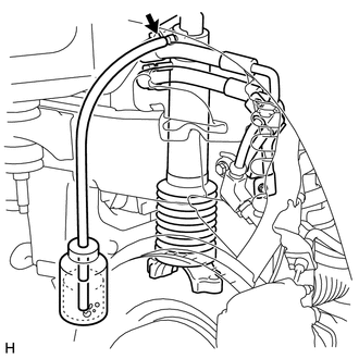
(a) Remove the stabilizer control valve protector (See page
.gif) ).
).
(b) Check the pipe connections and whether or not any hydraulic circuit parts are damaged.
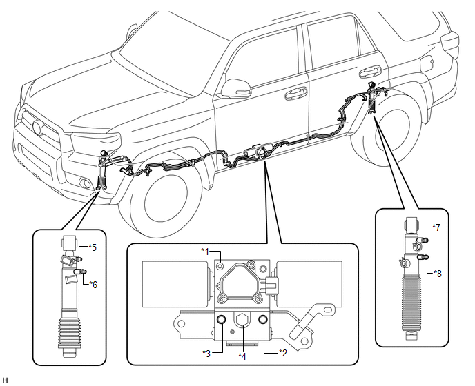 Text in Illustration
|
*1 |
Stabilizer Control with Accumulator Housing Bleeder Plug |
*2 |
Upper Chamber Stabilizer Control with Accumulator Housing Shutter Valve |
|
*3 |
Lower Chamber Stabilizer Control with Accumulator Housing Shutter Valve |
*4 |
Stabilizer Control Accumulator Housing Inlet Port |
|
*5 |
Front Stabilizer Control Cylinder Upper Chamber Bleeder Plug |
*6 |
Front Stabilizer Control Cylinder Lower Chamber Bleeder Plug |
|
*7 |
Rear Stabilizer Control Cylinder Upper Chamber Bleeder Plug |
*8 |
Rear Stabilizer Control Cylinder Lower Chamber Bleeder Plug |
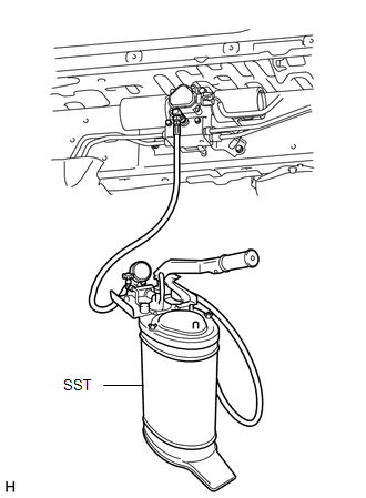
(c) Add new fluid to SST (high pressure oil pump) and bleed air from SST hoses.
SST: 09760-60020
Fluid:
Suspension fluid AHC
NOTICE:
If air is not bled from the hoses, the air will mix into the hydraulic circuit.
|
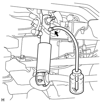
(d) Remove the service valve cap. Then put fluid into SST (high pressure oil pump) and connect SST to the suspension fluid inlet port. HINT:
|
|
(e) Loosen the shutter valves of the stabilizer control with accumulator housing.
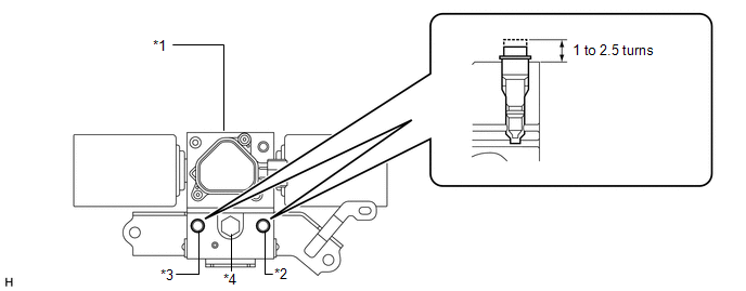 Text in Illustration
|
*1 |
Stabilizer Control with Accumulator Housing Assembly |
*2 |
Upper Chamber Stabilizer Control with Accumulator Housing Shutter Valve |
|
*3 |
Lower Chamber Stabilizer Control with Accumulator Housing Shutter Valve |
*4 |
Stabilizer Control Accumulator Housing Inlet Port |
NOTICE:
- When loosening a shutter valve, loosen it 1 to 2.5 turns, but do not loosen it any more than that.
- As air may enter the system or fluid may spray out, do not remove the shutter valves.
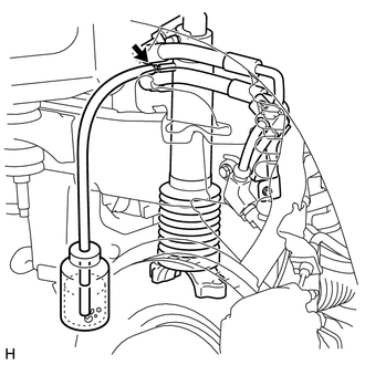
(f) Using SST (high pressure oil pump), add fluid.
CAUTION:
If a fluid leak is discovered, immediately release the pressure and repair the fluid leak as there is danger involved due to the high pressure.
NOTICE:
Do not allow the pressure to reach 8 MPa (81.6 kgf/cm2, 1160 psi) or higher as the accumulator may be damaged.
(1) Pump SST (high pressure oil pump) to add fluid until the pressure reaches 5 MPa (51.0 kgf/cm2, 725 psi).*1
(2) Check for fluid leaks from the pipe connections and hydraulic circuit parts.
|
(3) Add fluid to the stabilizer control with accumulator housing.*2
Torque: 8.3 N·m {85 kgf·cm, 73 in·lbf} |
|
.png)
|
(4) Add fluid to the lower chamber of the front stabilizer control cylinder.*3
Torque: 7.9 N·m {81 kgf·cm, 70 in·lbf} |
|
|
(5) Add fluid to the upper chamber of the front stabilizer control cylinder.*4
Torque: 7.9 N·m {81 kgf·cm, 70 in·lbf} |
|
|
(6) Add fluid to the lower chamber of the rear stabilizer control cylinder.*5
Torque: 7.9 N·m {81 kgf·cm, 70 in·lbf} |
|
|
(7) Add fluid to the upper chamber of the rear stabilizer control cylinder.*6
Torque: 7.9 N·m {81 kgf·cm, 70 in·lbf} |
|
(8) Repeat procedures *1 to *6 until the air in the fluid is gone.
(g) Using SST (high pressure oil pump), bleed the air.
NOTICE:
- Be sure to apply 7 MPa (71.4 kgf/cm2, 1015 psi) of pressure to all parts. If the pressure is low, the air may not be released.
- Do not allow the pressure to reach 8 MPa (81.6 kgf/cm2, 1160 psi) or higher as the accumulator may be damaged.
(1) Bleed air from the stabilizer control with accumulator housing.
- Pump SST (high pressure oil pump) to apply 7 MPa (71.4 kgf/cm2, 1015 psi) of pressure.
- Loosen the bleeder plug of the stabilizer control with accumulator housing to bleed the air.
- Tighten the bleeder plug so pressure can be applied. Repeat these steps until the air in the fluid is gone.
- Tighten the bleeder plug of the stabilizer control with accumulator housing.
Torque:
8.3 N·m {85 kgf·cm, 73 in·lbf}
(2) Bleed air from the upper chamber of the front stabilizer control cylinder.
- Pump SST (high pressure oil pump) to apply 7 MPa (71.4 kgf/cm2, 1015 psi) of pressure.
- Loosen the upper chamber bleeder plug of the front stabilizer control cylinder to bleed the air.
- Tighten the bleeder plug so pressure can be applied. Repeat these steps until the air in the fluid is gone.
- Tighten the upper chamber bleeder plug of the front stabilizer control cylinder.
Torque:
7.9 N·m {81 kgf·cm, 70 in·lbf}
(3) Bleed air from the upper chamber of the rear stabilizer control cylinder.
- Pump SST (high pressure oil pump) to apply 7 MPa (71.4 kgf/cm2, 1015 psi) of pressure.
- Loosen the upper chamber bleeder plug of the rear stabilizer control cylinder to bleed the air.
- Tighten the bleeder plug so pressure can be applied. Repeat these steps until the air in the fluid is gone.
- Tighten the upper chamber bleeder plug of the rear stabilizer control cylinder.
Torque:
7.9 N·m {81 kgf·cm, 70 in·lbf}
|
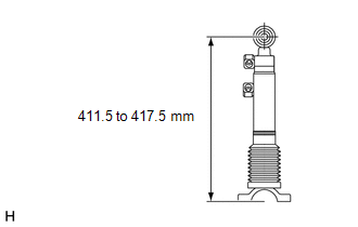
(h) Disconnect the front stabilizer control arm and front stabilizer link, and set the front stabilizer control cylinder to the maximum length. Maximum length: 411.5 to 417.5 mm (16.2 to 16.4 in.) NOTICE: Set the front stabilizer control cylinder to the maximum length to completely bleed the air. HINT: Refer to the following procedures to disconnect the front stabilizer
control arm and front stabilizer link (See page
|
|
|
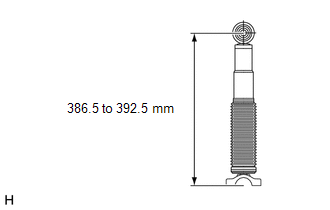
(i) Disconnect the rear stabilizer bar and rear stabilizer link, and set the rear stabilizer control cylinder to the maximum length. Maximum length: 386.5 to 392.5 mm (15.2 to 15.4 in.) NOTICE: Set the rear stabilizer control cylinder to the maximum length to completely bleed the air. HINT: Refer to the following procedures to disconnect the rear stabilizer bar
and rear stabilizer link (See page |
|
(j) Bleed air from the lower chamber of the front stabilizer control cylinder.
(1) Pump SST (high pressure oil pump) to apply 7 MPa (71.4 kgf/cm2, 1015 psi) of pressure.
(2) Loosen the lower chamber bleeder plug of the front stabilizer control cylinder to bleed the air.
(3) Tighten the bleeder plug so pressure can be applied. Repeat these steps until the air in the fluid is gone.
(4) Tighten the lower chamber bleeder plug of the front stabilizer control cylinder.
Torque:
7.9 N·m {81 kgf·cm, 70 in·lbf}
(k) Bleed air from the lower chamber of the rear stabilizer control cylinder.
(1) Pump SST (high pressure oil pump) to apply 7 MPa (71.4 kgf/cm2, 1015 psi) of pressure.
(2) Loosen the lower chamber bleeder plug of the rear stabilizer control cylinder to bleed the air.
(3) Tighten the bleeder plug so pressure can be applied. Repeat these steps until the air in the fluid is gone.
(4) Tighten the lower chamber bleeder plug of the rear stabilizer control cylinder.
Torque:
7.9 N·m {81 kgf·cm, 70 in·lbf}
(l) Connect the front stabilizer control arm to the front stabilizer link and the rear stabilizer bar to the rear stabilizer link.
HINT:
- For the front side, refer to the following procedures (See page
).
- For the rear side, refer to the following procedures (See page
).
(m) With all wheels on the ground, apply the specified amount of pressure using SST. Maintain this pressure for 2 to 3 minutes to stabilize the pressure.
NOTICE:
- Refer to the Temperature Management Chart when Filling Fluid as the specified pressure changes according to the fluid temperature.
- Perform the inspection with the vehicle empty.
- Perform the inspection with the vehicle load completely on the suspension.
Standard Fluid Pressure:
|
Condition |
Specified Condition |
|---|---|
|
Fluid temperature is 20°C (68°F) |
2.6 to 3 MPa (26.6 to 30.5 kgf/cm2, 377 to 435 psi) |
(n) Measure vehicle height (See page ).
(o) Tighten the shutter valves of the stabilizer control with accumulator housing.
Torque:
9.0 N·m {92 kgf·cm, 80 in·lbf}
(p) Remove SST (high pressure oil pump) from the suspension fluid inlet port.
NOTICE:
Make sure that no pressure is applied to SST (high pressure oil pump).
(q) Install the service valve caps to the suspension fluid inlet port.
Torque:
0.6 N·m {6.0 kgf·cm, 5.0 in·lbf}
(r) Inspect for suspension fluid leaks (See page
).
(s) Install the stabilizer control valve protector (See page
).
2. TEMPERATURE MANAGEMENT CHART WHEN FILLING FLUID
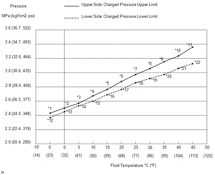 Text in Illustration
|
*1 |
2.42 MPa (24.7 kgf/cm2, 351 psi) |
*2 |
2.50 MPa (25.5 kgf/cm2, 363 psi) |
|
*3 |
2.59 MPa (26.4 kgf/cm2, 376 psi) |
*4 |
2.67 MPa (27.2 kgf/cm2, 387 psi) |
|
*5 |
2.76 MPa (28.1 kgf/cm2, 400 psi) |
*6 |
2.85 MPa (29.1 kgf/cm2, 413 psi) |
|
*7 |
2.95 MPa (30.1 kgf/cm2, 428 psi) |
*8 |
3.05 MPa (31.1 kgf/cm2, 442 psi) |
|
*9 |
3.16 MPa (32.2 kgf/cm2, 458 psi) |
*10 |
3.27 MPa (33.3 kgf/cm2, 474 psi) |
|
*11 |
3.38 MPa (34.5 kgf/cm2, 490 psi) |
*12 |
2.39 MPa (24.4 kgf/cm2, 347 psi) |
|
*13 |
2.46 MPa (25.1 kgf/cm2, 357 psi) |
*14 |
2.53 MPa (25.8 kgf/cm2, 367 psi) |
|
*15 |
2.60 MPa (26.5 kgf/cm2, 377 psi) |
*16 |
2.67 MPa (27.2 kgf/cm2, 387 psi) |
|
*17 |
2.75 MPa (28.0 kgf/cm2, 399 psi) |
*18 |
2.82 MPa (28.8 kgf/cm2, 409 psi) |
|
*19 |
2.90 MPa (29.6 kgf/cm2, 421 psi) |
*20 |
2.98 MPa (30.4 kgf/cm2, 432 psi) |
|
*21 |
3.06 MPa (31.2 kgf/cm2, 444 psi) |
*22 |
3.14 MPa (32.0 kgf/cm2, 455 psi) |
 On-vehicle Inspection
ON-VEHICLE INSPECTION
PROCEDURE
1. INSPECT VEHICLE HEIGHT
NOTICE:
Perform the calibration on a level surface.
Perform the calibration with the vehicle empty.
Make sure that the whe ...
 Suspension Control System(w/ Reas)
Precaution
PRECAUTION
1. HANDLING PRECAUTIONS FOR CENTER UNIT AND SHOCK ABSORBER
(a) Replacement of each unit is allowed if there is no fluid leakage. However,
in the case of fluid leakage from ...
Other materials about Toyota 4Runner:
Installation
INSTALLATION
CAUTION / NOTICE / HINT
HINT:
A bolt without a torque specification is shown in the standard bolt chart (See
page ).
PROCEDURE
1. INSTALL INSTRUMENT PANEL SUB-ASSEMBLY
(a) Attach the 2 guides to install the instrument panel sub-assembly.
...
Operation Check
OPERATION CHECK
1. INSPECT INDICATOR/WARNING LIGHT
(a) Check the following indicators and warning lights.
Indicator/Warning Light
Switch Condition
Specified Condition
Tire pressure warning light
I ...

0.0202