Toyota 4Runner: Center Airbag Sensor Communication Stop Mode
DESCRIPTION
|
Detection Item |
Symptom |
Trouble Area |
|---|---|---|
|
Center Airbag Sensor Communication Stop Mode |
Either condition is met:
|
|
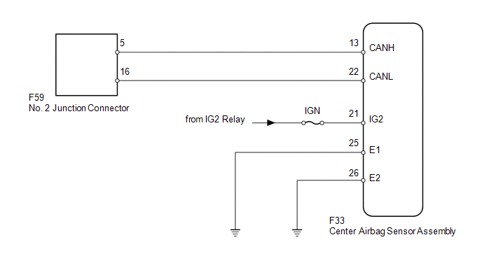
WIRING DIAGRAM
CAUTION / NOTICE / HINT
NOTICE:
Inspect the fuses for circuits related to this system before performing the following inspection procedure.
HINT:
Operating the ignition switch, any switches or any doors triggers related ECU and sensor communication with the CAN, which causes resistance variation.
PROCEDURE
|
1. |
DISCONNECT CABLE FROM NEGATIVE BATTERY TERMINAL |
(a) Disconnect the cable from the negative (-) battery terminal before measuring the resistances of the main wire and branch wire.
CAUTION:
Wait at least 90 seconds after disconnecting the cable from the negative (-) battery terminal to disable the SRS system.
NOTICE:
When disconnecting the cable, some systems need to be initialized after the cable
is reconnected (See page .gif) ).
).
|
.gif)
|
2. |
CHECK FOR OPEN IN CAN BUS WIRE (CENTER AIRBAG SENSOR ASSEMBLY BRANCH WIRE) |
|
(a) Disconnect the F33 center airbag sensor assembly connector. |
|
(b) Measure the resistance according to the value(s) in the table below.
Standard Resistance:
|
Tester Connection |
Switch Condition |
Specified Condition |
|---|---|---|
|
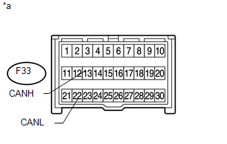
F33-13 (CANH) - F33-22 (CANL) |
Ignition switch off |
54 to 69 Ω |
|
*a |
Front view of wire harness connector (to Center Airbag Sensor Assembly) |
| NG | .gif) |
REPAIR OR REPLACE CENTER AIRBAG SENSOR ASSEMBLY BRANCH WIRE OR CONNECTOR (CANH, CANL) |
|
|
3. |
CHECK HARNESS AND CONNECTOR (CENTER AIRBAG SENSOR ASSEMBLY - BATTERY AND BODY GROUND) |
|
(a) Connect the cable to the negative (-) battery terminal. NOTICE: When disconnecting the cable, some systems need to be initialized after
the cable is reconnected (See page |
|
(b) Measure the resistance according to the value(s) in the table below.
Standard Resistance:
|
Tester Connection |
Condition |
Specified Condition |
|---|---|---|
|
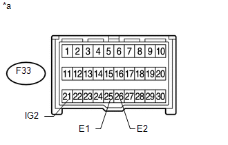
F33-25 (E1) - Body ground |
Always |
Below 1 Ω |
|
F33-26 (E2) - Body ground |
(c) Measure the voltage according to the value(s) in the table below.
Standard Voltage:
|
Tester Connection |
Switch Condition |
Specified Condition |
|---|---|---|
|
F33-21 (IG2) - Body ground |
Ignition switch ON |
11 to 14 V |
|
*a |
Front view of wire harness connector (to Center Airbag Sensor Assembly) |
| OK | |
REPLACE CENTER AIRBAG SENSOR ASSEMBLY |
| NG | |
REPAIR OR REPLACE HARNESS OR CONNECTOR |
 Certification ECU Communication Stop Mode
DESCRIPTION
Detection Item
Symptoms
Trouble Area
Certification ECU Communication Stop Mode
Either condition is met:
"Ce ...
 4WD Control ECU Communication Stop Mode
DESCRIPTION
Detection Item
Symptom
Trouble Area
4WD Control ECU Communication Stop Mode
Either condition is met:
"Four ...
Other materials about Toyota 4Runner:
Driver Side Seat Belt Warning Light does not Operate
DESCRIPTION
When the ignition switch is turned to ON, the center airbag sensor transmits
front seat inner belt LH state signals to the combination meter through the CAN.
If the driver side seat belt is not fastened, the combination meter blinks the driver ...
Diagnostic Trouble Code Chart
DIAGNOSTIC TROUBLE CODE CHART
HINT:
If a trouble code is output during the DTC check, inspect the trouble areas listed
for that code. For details of the code, refer to the "See page" below.
Sliding Roof System
DTC Code
Det ...
0.0174