Toyota 4Runner: Communication Malfunction No. 1 (B2797)
DESCRIPTION
This DTC is stored when a communication error occurs between the transponder key amplifier and transponder key ECU assembly. Some possible reasons for the communication error are: 1) 2 or more ignition keys are positioned too close together, or 2) noise is occurring in the communication line.
|
DTC Code |
DTC Detection Condition |
Trouble Area |
|---|---|---|
|
B2797 |
2 or more ignition keys are positioned too close to each other or noise occurs in the communication line. |
|
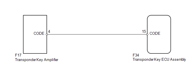
WIRING DIAGRAM
CAUTION / NOTICE / HINT
NOTICE:
When the transponder key ECU assembly is replaced, refer to Registration (See
page .gif) ).
).
PROCEDURE
|
1. |
CHECK KEY |
|
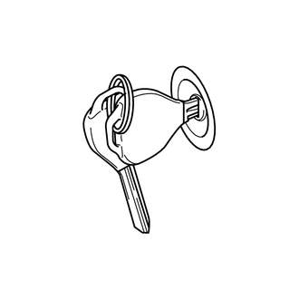
(a) Check whether the ignition key being used is near other ignition keys, as shown in the illustration. Also, check whether a key ring is in contact with the key grip. Result
|
|
| B | .gif) |
GO TO STEP 3 |
|
.gif)
|
2. |
CHECK FOR DTC |
(a) Separate the keys from each other or remove the key ring.
(b) Clear the DTCs (See page ).
(c) Insert a key into the ignition key cylinder, and then remove it. Repeat this for all the other keys.
(d) Check that no DTC is output (See page ).
OK:
DTC B2797 is not output.
| OK | |
END |
|
|
3. |
CHECK HARNESS AND CONNECTOR (TRANSPONDER KEY ECU - TRANSPONDER KEY AMPLIFIER) |
(a) Disconnect the F34 ECU connector.
(b) Disconnect the F17 amplifier connector.
(c) Measure the resistance according to the value(s) in the table below.
Standard Resistance:
|
Tester Connection |
Condition |
Specified Condition |
|---|---|---|
|
F34-15 (CODE) - F17-4 (CODE) |
Always |
Below 1 Ω |
|
F34-15 (CODE) or F17-4 (CODE) - Body ground |
Always |
10 kΩ or higher |
| NG | |
REPAIR OR REPLACE HARNESS OR CONNECTOR |
|
|
4. |
CHECK TRANSPONDER KEY ECU ASSEMBLY (NOISE) |
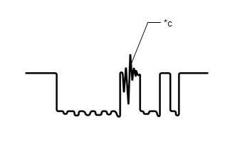
(a) Using an oscilloscope, check for noise in the waveform between the terminals of the F17 amplifier connector and F34 ECU connector.
 Measurement Condition
|
Item |
Content |
|---|---|
|
Tester Connection |
F17-4 (CODE) - F34-15 (CODE) |
|
Tool Setting |
5 V/DIV., 20 ms./DIV. |
|
Condition |
Key inserted in ignition key cylinder |
OK:
No noise is present.
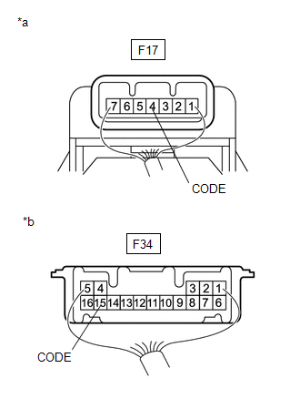
Text in Illustration|
*a |
Component with harness connected (Transponder Key Amplifier) |
|
*b |
Component with harness connected (Transponder Key ECU Assembly) |
|
*c |
Noise should not appear |
| NG | |
FIND CAUSE OF NOISE AND REMOVE IT |
|
|
5. |
REPLACE TRANSPONDER KEY AMPLIFIER |
(a) Temporarily replace the transponder key amplifier with a new or normally
functioning one (See page ).
|
|
6. |
CHECK WHETHER ENGINE STARTS |
(a) Check that the engine starts normally.
OK:
Engine starts.
| OK | |
END (TRANSPONDER KEY AMPLIFIER IS DEFECTIVE) |
| NG | |
REPLACE TRANSPONDER KEY ECU ASSEMBLY |
 Transponder Chip Malfunction (B2793-B2795)
DESCRIPTION
DTC B2793 is stored when a malfunction is found in the key during key
code registration or a key code is not registered normally. Replace the
key if key code registration c ...
 Engine Immobiliser System Malfunction (B2799)
DESCRIPTION
This DTC is stored when one of the following occurs: 1) the ECM detects errors
in its own communications with the transponder key ECU assembly; 2) the ECM detects
errors in the commun ...
Other materials about Toyota 4Runner:
Adjustment
ADJUSTMENT
PROCEDURE
1. CHECK BRAKE PEDAL HEIGHT
(a) Check the brake pedal height.
Pedal height from Floor panel:
158.8 to 168.8 mm (6.25 to 6.46 in.)
Text in Illustration
*a
Pedal Height
...
TS and CG Terminal Circuit
DESCRIPTION
The signal check circuit detects trouble in the sensor or switch signal which
cannot be detected by the DTC check.
Connecting terminals TS and CG of the DLC3 starts the check.
WIRING DIAGRAM
CAUTION / NOTICE / HINT
NOTICE:
When replacing ...
0.0066