Toyota 4Runner: Disassembly
DISASSEMBLY
PROCEDURE
1. REMOVE FRONT SUSPENSION UPPER ARM BUSH LH
HINT:
Use the same procedure for the front and rear sides.
|
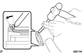
(a) Using a hammer and chisel, strike and bend the entire flange of the upper arm bush as shown in the illustration. |
|
|
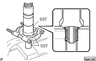
(b) Using SST and a press, press out the bush. SST: 09613-26010 SST: 09710-22021 09710-01031 SST: 09950-00020 |
|
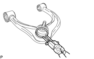
2. REMOVE FRONT UPPER BALL JOINT DUST COVER LH
|
(a) Using a snap ring expander, remove the dust cover set ring and dust cover from the upper arm. NOTICE:
|
|
 On-vehicle Inspection
ON-VEHICLE INSPECTION
PROCEDURE
1. INSPECT FRONT SUSPENSION UPPER ARM BALL JOINT RATTLE
(a) Jack up the vehicle.
(b) Move the front suspension upper arm up and down by hand and check for rattle.
...
 Removal
REMOVAL
CAUTION / NOTICE / HINT
HINT:
Use the same procedure for the RH and LH sides.
The procedure listed below is for the LH side.
PROCEDURE
1. REMOVE FRONT WHEEL
2. REMOVE S ...
Other materials about Toyota 4Runner:
Removal
REMOVAL
PROCEDURE
1. REMOVE FRONT BUMPER COVER (w/o Intuitive Parking Assist System)
(See Page )
2. REMOVE FRONT BUMPER COVER (w/ Intuitive Parking Assist System)
(See Page )
3. REMOVE HIGH PITCHED HORN ASSEMBLY
4. REMOVE RADIATOR GRILLE BRACKET
...
Data List / Active Test
DATA LIST / ACTIVE TEST
1. DATA LIST
NOTICE:
In the table below, the values listed under "Normal Condition" are reference
values. Do not depend solely on these reference values when deciding whether a part
is faulty or not.
HINT:
Using the T ...
0.01