Toyota 4Runner: Disassembly
DISASSEMBLY
PROCEDURE
1. REMOVE REAR BUMPER LOWER COVER (w/ Garnish)
|
(a) Remove the 2 clips and 14 outside moulding retainers. |
|
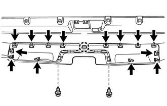
(b) Detach the claw to remove the rear bumper lower cover
2. REMOVE REAR BUMPER EXTENSION (w/o Pintle Hook)
|
(a) Remove the 2 clips and 2 outside moulding retainers. |
|
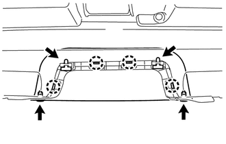
(b) Detach the 4 claws to remove the rear bumper extension.
3. REMOVE REAR BUMPER EXTENSION (w/ Pintle Hook)
|
(a) Remove the 2 clips and 2 outside moulding retainers. |
|
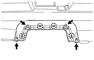
(b) Detach the 4 claws to remove the rear bumper extension.
4. REMOVE REAR BUMPER SIDE BRACKET LH
|
(a) Remove the clip and 2 screws. |
|
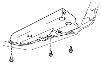
(b) Detach the guide to remove the rear bumper side bracket LH.
5. REMOVE REAR BUMPER SIDE BRACKET RH
HINT:
Use the same procedure as for the LH side.
 Removal
REMOVAL
PROCEDURE
1. REMOVE JACK BOX HOLE COVER
(a) Put protective around the jack box hole cover.
(b) Using a moulding remover, Detach th ...
 Reassembly
REASSEMBLY
PROCEDURE
1. INSTALL REAR BUMPER SIDE BRACKET LH
(a) Attach the guide.
(b) Install the rear bumper side bracket LH with the 2 screws and clip.
2. INSTALL REAR BUMPER SIDE BRACKET RH
H ...
Other materials about Toyota 4Runner:
System Description
SYSTEM DESCRIPTION
1. ILLUMINATION CONTROL SYSTEM (Illuminated Entry System)
(a) The illuminated entry system has the following control functions:
Control
Outline
Lighting
Actuation Area-linked*1
...
Checking and replacing fuses
If any of the electrical components do not operate, a fuse may have blown.
If this happens, check and replace the fuses as necessary.
Vehicles without a smart key
system Turn the engine switch off. Vehicles with a smart key
system
Turn the “ENGINE ...
0.0261