Toyota 4Runner: Disassembly
DISASSEMBLY
PROCEDURE
1. REMOVE NO. 1 POWER OUTLET SOCKET ASSEMBLY
.gif)
2. REMOVE NO. 1 POWER OUTLET SOCKET COVER
3. REMOVE REAR CONSOLE END PANEL
|
(a) Detach the 4 clips and 4 claws to remove the rear console end panel. |
|
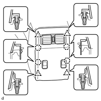
(b) Disconnect the 2 power outlet socket assembly connectors.
4. REMOVE NO. 3 POWER OUTLET SOCKET ASSEMBLY
5. REMOVE CENTER POWER OUTLET SOCKET COVER
6. REMOVE CONSOLE BOX REGISTER ASSEMBLY
|
(a) Detach the 4 claws to remove the console box register assembly. |
|
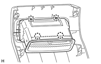
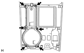
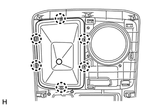
7. REMOVE CONSOLE COMPARTMENT DOOR SUB-ASSEMBLY
|
(a) Remove the 6 screws and console compartment door sub-assembly. |
|
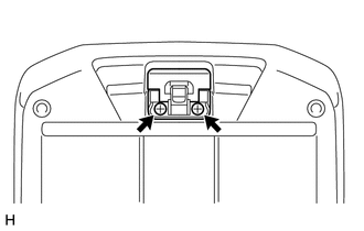
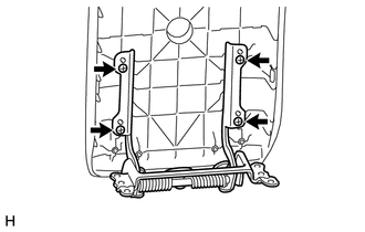
8. REMOVE CONSOLE COMPARTMENT DOOR LOCK SUB-ASSEMBLY
|
(a) Remove the 2 screws and console compartment door lock sub-assembly. |
|
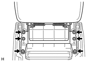
9. REMOVE CONSOLE COMPARTMENT DOOR HINGE SUB-ASSEMBLY
|
(a) Remove the 4 screws. |
|
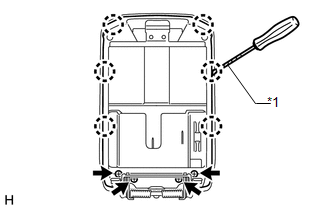
(b) Using a screwdriver, detach the 6 claws to remove the console compartment inner door.
Text in Illustration|
*1 |
Protective Tape |
HINT:
Tape the screwdriver tip before use.
|
(c) Remove the 4 screws and console compartment door hinge sub-assembly. |
|
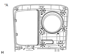
10. REMOVE CONSOLE CUP HOLDER BOX
|
(a) Remove the 6 screws and console cup holder box. |
|
11. REMOVE BACK DOOR POWER WINDOW REGULATOR SWITCH ASSEMBLY
12. REMOVE SEAT HEATER SWITCH (w/ Seat Heater System)
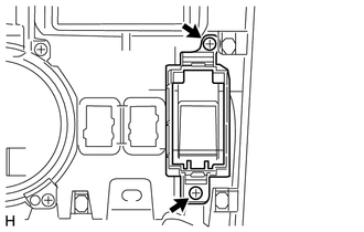
13. REMOVE SWITCH BASE
|
(a) Remove the 2 screws and switch base. |
|
14. REMOVE SHIFTING HOLE COVER SUB-ASSEMBLY (for VF2A)
|
(a) Detach the 6 claws to remove the shifting hole cover sub-assembly. |
|
15. REMOVE FRONT UPPER CONSOLE PANEL GARNISH
(a) for VF2A:
|
(1) Detach the 6 claws to remove the front upper console panel garnish. Text in Illustration
|
|
(b) for 2WD, for VF2BM, VF4BM:
(1) Detach the 10 claws to remove the front upper console panel garnish.
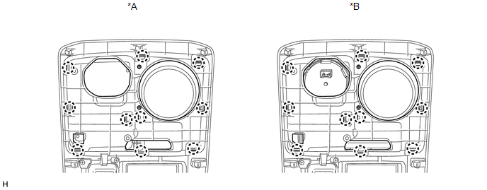 Text in Illustration
|
*A |
for 2WD |
*B |
for VF2BM, VF4BM |
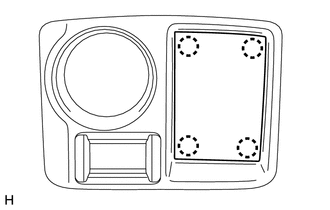
16. REMOVE NO. 2 BOX BOTTOM MAT (for 2WD)
|
(a) Detach the 4 claws to remove the No. 2 box bottom mat. |
|
17. REMOVE TRANSFER POSITION SWITCH (for VF2BM)
18. REMOVE TRANSFER POSITION SWITCH (for VF4BM)
 Components
COMPONENTS
ILLUSTRATION
ILLUSTRATION
ILLUSTRATION
ILLUSTRATION
...
 Removal
REMOVAL
PROCEDURE
1. REMOVE NO. 1 INSTRUMENT CLUSTER FINISH PANEL GARNISH
(a) Put protective tape around the No. 1 instrument cluster finish panel garnish.
(b) Grip the No. 1 instrument cluster fi ...
Other materials about Toyota 4Runner:
Room Temperature Sensor Circuit (B1411/11)
DESCRIPTION
The cooler thermistor (room temperature sensor) for the front seat is installed
in the instrument panel to detect the room temperature and control the heater and
air conditioner auto mode. The resistance of the room temperature sensor changes ...
Removal
REMOVAL
PROCEDURE
1. REMOVE REAR AXLE SHAFT LH
(a) Remove the rear axle shaft LH (See page
).
2. REMOVE REAR AXLE SHAFT RH
HINT:
Use the same procedure described for the LH side.
3. REMOVE PROPELLER SHAFT ASSEMBLY
(a) Remove the propeller shaft asse ...
0.0273