Toyota 4Runner: Disassembly
DISASSEMBLY
PROCEDURE
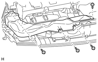
1. REMOVE NO. 1 HEATER TO REGISTER DUCT
|
(a) Remove the 4 screws and No. 1 heater to register duct. |
|
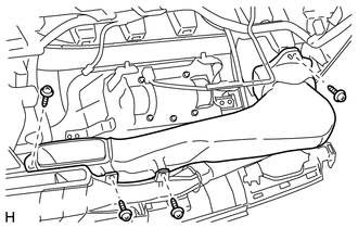
2. REMOVE NO. 2 HEATER TO REGISTER DUCT
|
(a) Remove the 4 screws and No. 2 heater to register duct. |
|
3. REMOVE NO. 1 SIDE DEFROSTER NOZZLE DUCT
|
(a) Remove the screw. |
|
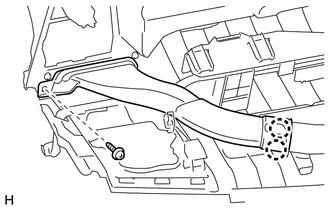
(b) Detach the 2 claws to remove the No. 1 side defroster nozzle duct.
4. REMOVE NO. 2 SIDE DEFROSTER NOZZLE DUCT
|
(a) Remove the screw. |
|
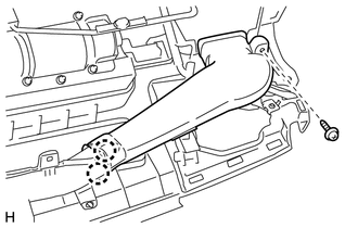
(b) Detach the 2 claws to remove the No. 2 side defroster nozzle duct.
5. REMOVE NO. 3 HEATER TO REGISTER DUCT
|
(a) Remove the 2 screws. |
|
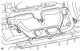
(b) Detach the claw to remove the No. 3 heater to register duct.
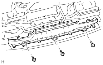
6. REMOVE DEFROSTER NOZZLE ASSEMBLY
|
(a) Remove the 3 screws and defroster nozzle assembly. |
|
7. REMOVE ACCESSORY METER ASSEMBLY
.gif)
8. REMOVE TELLTALE LIGHT ASSEMBLY
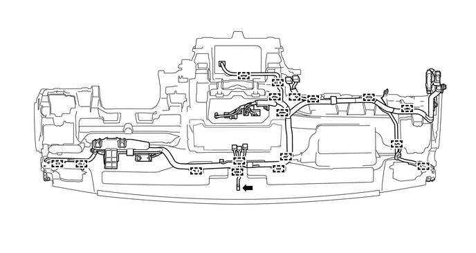
9. REMOVE NO. 2 INSTRUMENT PANEL WIRE
(a) Disconnect the connector.
(b) Detach the 17 clamps to remove the No. 2 instrument panel wire.
10. REMOVE INSTRUMENT PANEL PASSENGER AIRBAG ASSEMBLY
11. REMOVE AUTOMATIC LIGHT CONTROL SENSOR
12. REMOVE NAVIGATION ANTENNA ASSEMBLY (w/ Navigation System)
 Removal
REMOVAL
PROCEDURE
1. TABLE OF BOLT, SCREW AND NUT
HINT:
All bolts, screws and nuts relevant to installing and removing the instrument
panel are shown along with their alphabet code in the table ...
 Reassembly
REASSEMBLY
PROCEDURE
1. INSTALL NAVIGATION ANTENNA ASSEMBLY (w/ Navigation System)
2. INSTALL AUTOMATIC LIGHT CONTROL SENSOR
3. INSTALL INSTRUMENT PANEL PASSENGER AIRBAG ASSEMBLY
4. INST ...
Other materials about Toyota 4Runner:
How To Proceed With Troubleshooting
CAUTION / NOTICE / HINT
HINT:
Use these procedures to troubleshoot the automatic running board system.
PROCEDURE
1.
VEHICLE BROUGHT TO WORKSHOP
NEXT
...
Security Horn Circuit
DESCRIPTION
When the theft deterrent system is in the alarm sounding state, the main body
ECU outputs a signal repeatedly at 0.4 second intervals, causing the security horn
assembly to sound
WIRING DIAGRAM
CAUTION / NOTICE / HINT
NOTICE:
Inspect the ...
0.0132