Toyota 4Runner: Disassembly
DISASSEMBLY
CAUTION / NOTICE / HINT
HINT:
- Use the same procedure for the RH and LH sides.
- The procedure listed below is for the LH side.
PROCEDURE
1. REMOVE REAR WHEEL
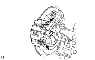
2. DISCONNECT REAR DISC BRAKE CYLINDER ASSEMBLY LH
|
(a) Remove the 2 bolts and disconnect the rear disc brake cylinder. NOTICE:
|
|
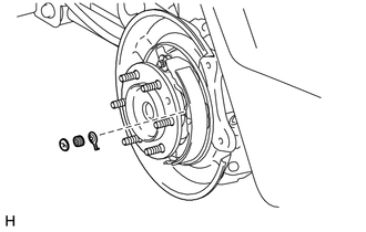
3. REMOVE REAR DISC
.gif)
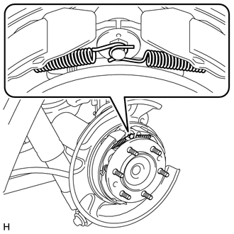
4. REMOVE PARKING BRAKE SHOE RETURN TENSION SPRING
|
(a) Remove the 2 parking brake shoe return tension springs. |
|
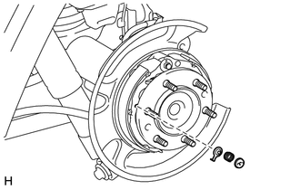
5. DISCONNECT NO. 1 PARKING BRAKE SHOE ASSEMBLY LH
|
(a) Remove the parking brake shoe hold down spring cup and parking brake shoe hold down spring to disconnect the No. 1 parking brake shoe assembly from the backing plate. |
|
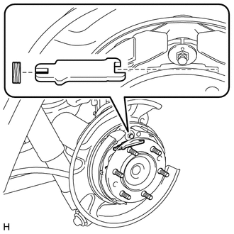
6. REMOVE PARKING BRAKE SHOE STRUT LH
|
(a) Remove the parking brake shoe strut and parking brake shoe strut compression spring. |
|
7. DISCONNECT NO. 2 PARKING BRAKE SHOE ASSEMBLY LH
|
(a) Remove the parking brake shoe hold down spring cup and parking brake shoe hold down spring to disconnect the No. 2 parking brake shoe assembly from the backing plate. |
|
8. REMOVE PARKING BRAKE SHOE ADJUSTING SCREW SET
|
(a) Remove the parking brake shoe adjusting screw set. |
|
9. REMOVE NO. 1 PARKING BRAKE SHOE ASSEMBLY LH
|
(a) Disconnect the parking brake shoe return tension spring to remove the No. 1 parking brake shoe assembly. |
|
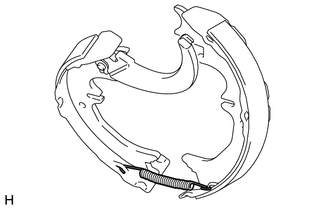
10. REMOVE PARKING BRAKE SHOE RETURN TENSION SPRING
|
(a) Remove the parking brake shoe return tension spring from the No. 2 parking brake shoe assembly. |
|
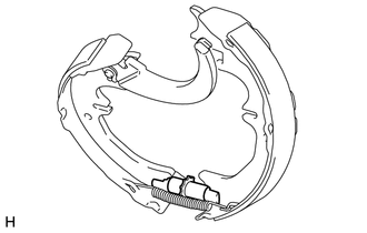
11. REMOVE NO. 2 PARKING BRAKE SHOE ASSEMBLY WITH PARKING BRAKE SHOE LEVER
|
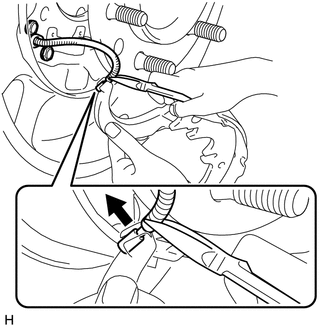
(a) Using needle-nose pliers, disconnect the No. 3 parking brake cable assembly from the parking brake shoe lever as shown in the illustration. NOTICE: Be careful not to damage the No. 3 parking brake cable assembly. |
|
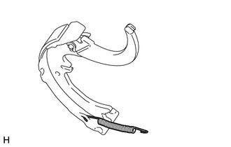
12. REMOVE PARKING BRAKE SHOE LEVER
|
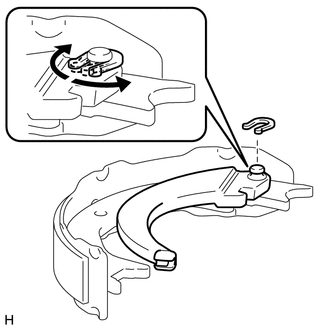
(a) Remove the C-washer, shim and parking brake shoe lever from the No. 2 parking brake shoe assembly as shown in the illustration. |
|
13. REMOVE PARKING BRAKE SHOE HOLD DOWN SPRING PIN
(a) Remove the parking brake shoe hold down spring pin (for front side).
(b) Remove the parking brake shoe hold down spring pin (for rear side).
 Components
COMPONENTS
ILLUSTRATION
...
 Inspection
INSPECTION
PROCEDURE
1. CHECK BRAKE DISC INSIDE DIAMETER
(a) Using a brake drum gauge or equivalent, measure the inside diameter
of the disc.
Standard inside diameter:
210 mm ...
Other materials about Toyota 4Runner:
Speed Signal Circuit
DESCRIPTION
The vehicle speed signal consists of pulses sent to the combination meter assembly
from the master cylinder solenoid (skid control ECU)*1 or skid control ECU (brake
actuator assembly)*2.
*1: for 4WD
*2: for 2WD
WIRING DIAGRA ...
Inspection
INSPECTION
PROCEDURE
1. INSPECT SPIRAL CABLE SUB-ASSEMBLY
(a) If there are any defects as mentioned below, replace the spiral cable with
a new one:
Scratches, cracks, dents or chips in the connector or spiral cable.
(b) Check the spiral cable.
Text in ...
0.007