Toyota 4Runner: Door Courtesy Switch Circuit
DESCRIPTION
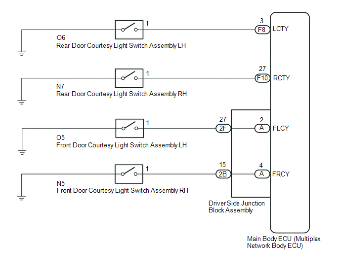
The main body ECU (multiplex network body ECU) receives a door open/closed signal from each door courtesy light switch.
WIRING DIAGRAM
PROCEDURE
|
1. |
READ VALUE USING TECHSTREAM (DOOR COURTESY LIGHT SWITCH) |
(a) Using the Techstream, read the Data List (See page
.gif) ).
).
Main Body
|
Tester Display |
Measurement Item/Range |
Normal Condition |
Diagnostic Note |
|---|---|---|---|
|
RR Door Courtesy SW |
Rear door courtesy light switch RH signal / ON or OFF |
ON: Rear door RH open OFF: Rear door RH closed |
- |
|
RL Door Courtesy SW |
Rear door courtesy light switch LH signal / ON or OFF |
ON: Rear door LH open OFF: Rear door LH closed |
- |
|
FR Door Courtesy SW |
Front door courtesy light switch RH signal / ON or OFF |
ON: Front door RH open OFF: Front door RH closed |
- |
|
FL Door Courtesy SW |
Front door courtesy light switch LH signal / ON or OFF |
ON: Front door LH open OFF: Front door LH closed |
- |
OK:
Normal conditions listed above are displayed.
Result|
Result |
Proceed to |
|---|---|
|
OK |
A |
|
NG (Front door courtesy light switch does not operate) |
B |
|
NG (Rear door courtesy light switch does not operate) |
C |
| A | .gif) |
PROCEED TO NEXT SUSPECTED AREA SHOWN IN PROBLEM SYMPTOMS TABLE |
| C | |
GO TO STEP 5 |
|
.gif)
|
2. |
INSPECT FRONT DOOR COURTESY LIGHT SWITCH ASSEMBLY (LH OR RH) |
|
(a) Remove the front door courtesy light switch assembly (See page
|
|
(b) Measure the resistance according to the value(s) in the table below.
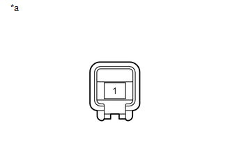
Text in Illustration|
*a |
Component without harness connected (Front Door Courtesy Light Switch Assembly) |
Standard Resistance:
|
Tester Connection |
Switch Condition |
Specified Condition |
|---|---|---|
|
1 - Switch body |
Pin not pushed |
Below 1 Ω |
|
Pin pushed |
10 kΩ or higher |
| NG | |
REPLACE FRONT DOOR COURTESY LIGHT SWITCH ASSEMBLY |
|
|
3. |
CHECK HARNESS AND CONNECTOR (FRONT DOOR COURTESY LIGHT SWITCH ASSEMBLY - MAIN BODY ECU) |
(a) Disconnect the O5*1 or N5*2 front door courtesy light switch assembly connector.
(b) Remove the main body ECU (multiplex network body ECU) (See page
).
(c) Measure the resistance according to the value(s) in the table below.
- *1: for LH
- *2: for RH
Standard Resistance:
for LH
|
Tester Connection |
Condition |
Specified Condition |
|---|---|---|
|
O5-1 - 2F-27 |
Always |
Below 1 Ω |
|
O5-1 - Body ground |
Always |
10 kΩ or higher |
for RH
|
Tester Connection |
Condition |
Specified Condition |
|---|---|---|
|
N5-1 - 2B-15 |
Always |
Below 1 Ω |
|
N5-1 - Body ground |
Always |
10 kΩ or higher |
| NG | |
REPAIR OR REPLACE HARNESS OR CONNECTOR |
|
|
4. |
INSPECT DRIVER SIDE JUNCTION BLOCK ASSEMBLY |
(a) Remove the driver side junction block assembly (See page
).
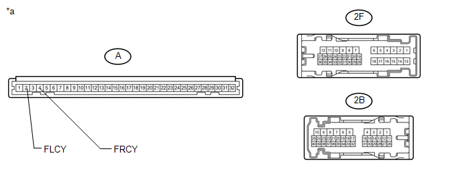 Text in Illustration
|
*a |
Component without harness connected (Driver Side Junction Block Assembly) |
- |
- |
(b) Remove the main body ECU (multiplex network body ECU) from the driver side junction block assembly.
(c) Measure the resistance according to the value(s) in the table below.
Standard Resistance:
|
Tester Connection |
Condition |
Specified Condition |
|---|---|---|
|
2F-27 - A-2 (FLCY) |
Always |
Below 1 Ω |
|
2B-15 - A-4 (FRCY) |
Always |
Below 1 Ω |
| OK | |
REPLACE MAIN BODY ECU (MULTIPLEX NETWORK BODY ECU) |
| NG | |
REPLACE DRIVER SIDE JUNCTION BLOCK ASSEMBLY |
|
5. |
INSPECT REAR DOOR COURTESY LIGHT SWITCH ASSEMBLY (LH OR RH) |
|
(a) Remove the rear door courtesy light switch assembly (See page
|
|
(b) Measure the resistance according to the value(s) in the table below.
Text in Illustration|
*a |
Component without harness connected (Rear Door Courtesy Light Switch Assembly) |
Standard Resistance:
|
Tester Connection |
Switch Condition |
Specified Condition |
|---|---|---|
|
1 - Switch body |
Pin not pushed |
Below 1 Ω |
|
Pin pushed |
10 kΩ or higher |
| NG | |
REPLACE REAR DOOR COURTESY LIGHT SWITCH ASSEMBLY |
|
|
6. |
CHECK HARNESS AND CONNECTOR (REAR DOOR COURTESY LIGHT SWITCH ASSEMBLY - MAIN BODY ECU) |
(a) Disconnect the O6*1 or N7*2 rear door courtesy light switch assembly connector.
(b) Disconnect the F8 or F10 main body ECU (multiplex network body ECU) connector.
(c) Measure the resistance according to the value(s) in the table below.
- *1: for LH
- *2: for RH
Standard Resistance:
for LH
|
Tester Connection |
Condition |
Specified Condition |
|---|---|---|
|
O6-1 - F8-3 (LCTY) |
Always |
Below 1 Ω |
|
O6-1 - Body ground |
Always |
10 kΩ or higher |
for RH
|
Tester Connection |
Condition |
Specified Condition |
|---|---|---|
|
N7-1 - F10-27 (RCTY) |
Always |
Below 1 Ω |
|
N7-1 - Body ground |
Always |
10 kΩ or higher |
| OK | |
REPLACE MAIN BODY ECU (MULTIPLEX NETWORK BODY ECU) |
| NG | |
REPAIR OR REPLACE HARNESS OR CONNECTOR |
 Back Door Courtesy Switch Circuit
DESCRIPTION
The multiplex network door ECU receives a back door open/closed signal from the
back door lock.
WIRING DIAGRAM
PROCEDURE
1.
READ VALUE USING TECHSTREAM (BACK ...
 Interior Light Auto Cut Circuit
DESCRIPTION
The main body ECU (multiplex network body ECU) controls operation of the DOME
relay in order to supply power to the interior lights. When battery saving control
operates while the int ...
Other materials about Toyota 4Runner:
Inspection
INSPECTION
CAUTION / NOTICE / HINT
NOTICE:
The master cylinder and piston are designed so that the piston can easily
fall out. Prevent this by making sure the tip of the master cylinder faces
downward when handling the master cylinder.
M ...
Portable Player cannot be Connected Manually/Automatically
CAUTION / NOTICE / HINT
HINT:
Some versions of "Bluetooth" compatible audio players may not function, or the
function may be limited using the radio and display receiver assembly, even if the
portable audio player itself can play files (See pag ...
0.0107