Toyota 4Runner: Front Seat Inner Belt Assembly
Components
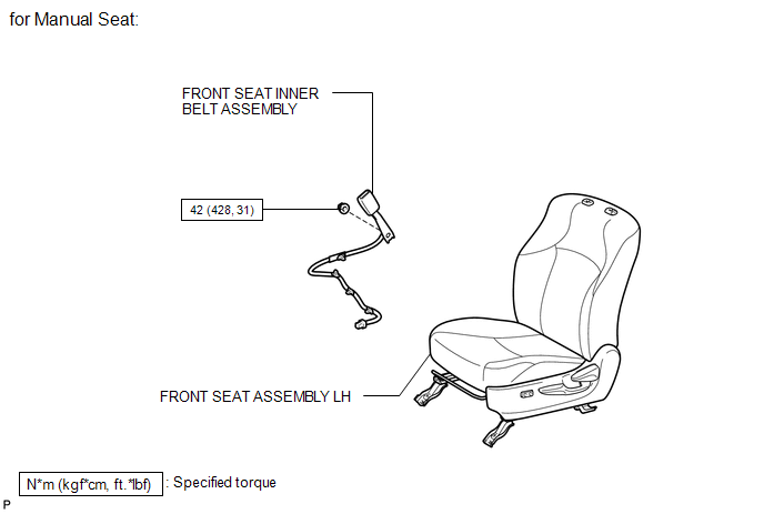
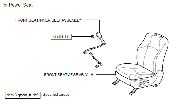
COMPONENTS
ILLUSTRATION
ILLUSTRATION
Installation
INSTALLATION
CAUTION / NOTICE / HINT
HINT:
- Use the same procedure for the RH and LH sides.
- The procedure listed below is for the LH side.
PROCEDURE
1. INSTALL FRONT SEAT INNER BELT ASSEMBLY LH
|
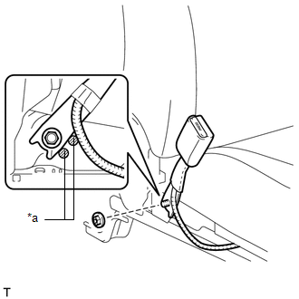
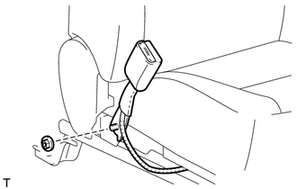
(a) Install the front seat inner belt with the nut. Torque: 42 N·m {428 kgf·cm, 31 ft·lbf} NOTICE: Do not allow the anchor part of the front seat inner belt assembly to overlap the protruding parts of the front seat adjuster. Text in Illustration
|
|
(b) for Driver Side:
Connect the connector and attach the 4 clamps.
(c) for Passenger Side:
Connect the connector and attach the clamp.
2. INSTALL FRONT SEAT ASSEMBLY LH
(a) for Manual Seat:
Install the front seat assembly LH (See page .gif)
).
(b) for Power Seat:
Install the front seat assembly LH (See page
).
Removal
REMOVAL
CAUTION / NOTICE / HINT
HINT:
- Use the same procedure for the RH and LH sides.
- The procedure listed below is for the LH side.
PROCEDURE
1. REMOVE FRONT SEAT ASSEMBLY LH
(a) for Manual Seat:
Remove the front seat assembly LH (See page .gif)
).
(b) for Power Seat:
Remove the front seat assembly LH (See page
).
2. REMOVE FRONT SEAT INNER BELT ASSEMBLY LH
(a) for Driver Side:
Disconnect the connector and detach the 4 clamps.
(b) for Passenger Side:
Disconnect the connector and detach the clamp.
|
(c) Remove the nut and front seat inner belt. |
|
 Seat Belt
...

Other materials about Toyota 4Runner:
Disassembly
DISASSEMBLY
PROCEDURE
1. REMOVE FRONT NO. 1 LOWER ARM BUSH LH
(a) Using a chisel and hammer, pry the flange of the bush outward.
(b) Using SST and a press, press out the bush.
SST: 09632-36 ...
Rear Upper Arm
Components
COMPONENTS
ILLUSTRATION
Removal
REMOVAL
CAUTION / NOTICE / HINT
HINT:
Use the same procedure for the RH and LH sides.
The procedure listed below is for the LH side.
PROCEDURE
1. REMOVE REAR WHEEL
2. REMOVE REAR UPPE ...
0.0251