Toyota 4Runner: Headlight Relay Circuit
DESCRIPTION
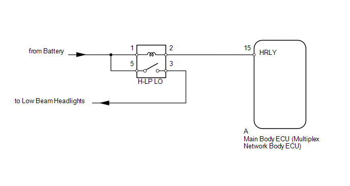
The main body ECU receives headlight dimmer switch information signals, and illuminates the low beam headlight.
WIRING DIAGRAM
CAUTION / NOTICE / HINT
NOTICE:
Inspect the fuses and bulbs for circuits related to this system before performing the following inspection procedure.
PROCEDURE
|
1. |
PERFORM ACTIVE TEST USING TECHSTREAM (HEADLIGHT RELAY) |
(a) Using the Techstream, perform the Active Test (See page
.gif) ).
).
Main Body
|
Tester Display |
Test Part |
Control Range |
Diagnostic Note |
|---|---|---|---|
|
Headlight Relay |
Low beam headlight relay |
ON/OFF |
- |
OK:
Headlight relay operates (low beam headlights illuminate).
| OK | .gif) |
PROCEED TO NEXT SUSPECTED AREA SHOWN IN PROBLEM SYMPTOMS TABLE |
|
.gif)
|
2. |
INSPECT HEADLIGHT RELAY (H-LP LO) |
|
(a) Remove the headlight relay from the engine room relay block, junction block. |
|
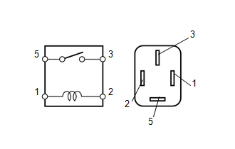
(b) Measure the resistance according to the value(s) in the table below.
Standard Resistance:
|
Tester Connection |
Condition |
Specified Condition |
|---|---|---|
|
3 - 5 |
Battery voltage not applied between terminals 1 and 2 |
10 kΩ or higher |
|
Battery voltage applied between terminals 1 and 2 |
Below 1 Ω |
| NG | |
REPLACE HEADLIGHT RELAY |
|
|
3. |
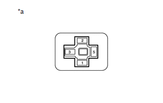
CHECK HARNESS AND CONNECTOR (BATTERY - HEADLIGHT RELAY [H-LP LO]) |
|
(a) Measure the voltage according to the value(s) in the table below. Standard Voltage:
|
|
| NG | |
REPAIR OR REPLACE HARNESS OR CONNECTOR |
|
|
4. |
CHECK HARNESS AND CONNECTOR (HEADLIGHT RELAY [H-LP LO] - MAIN BODY ECU) |
(a) Remove the main body ECU (See page ).
(b) Measure the resistance according to the value(s) in the table below.
Standard Resistance:
|
Tester Connection |
Condition |
Specified Condition |
|---|---|---|
|
Headlight relay terminal 2 - A-15 (HRLY) |
Always |
Below 1 Ω |
|
A-15 (HRLY) - Body ground |
Always |
10 kΩ or higher |
| OK | |
PROCEED TO NEXT SUSPECTED AREA SHOWN IN PROBLEM SYMPTOMS TABLE |
| NG | |
REPAIR OR REPLACE HARNESS OR CONNECTOR |
 Headlight Dimmer Switch Circuit
DESCRIPTION
The main body ECU receives the following signals:
Headlight dimmer switch tail, head, AUTO*, high or high flash signal
Front fog light switch signal
*: w/ Aut ...
 Headlight (HI-BEAM) Circuit
DESCRIPTION
The main body ECU (multiplex network body ECU) receives headlight dimmer switch
information signals, and illuminates the high beam headlight.
WIRING DIAGRAM
CAUTION / NOTICE / HINT
...
Other materials about Toyota 4Runner:
Switching the display
Items displayed can be switched by pressing the display change button.
Odometer
Displays the total distance the vehicle has been driven.
Trip meter
Displays the distance the vehicle has been driven since the meter was last
reset. Trip meters “A” ...
Crawl Control
Allows travel on extremely rough off-road surfaces at a fixed low speed
without pressing the accelerator or brake pedal. Minimizes loss of traction or
vehicle slip when driving on slippery road surfaces, allowing for stable
driving.
Crawl Control switch ...
0.0105