Toyota 4Runner: Inspection
INSPECTION
PROCEDURE
1. INSPECT TIE ROD END SUB-ASSEMBLY
|
(a) Install the nut. |
|
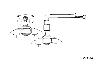
(b) Flip the ball joint stud back and forth 5 times as shown in the illustration.
(c) Using a torque wrench, turn the nut continuously at a rate of 3 to 5 seconds per turn and check the torque reading on the 5th turn.
Standard Torque:
1.0 to 3.9 N*m (10 to 39 kgf*cm, 9 to 34 in.*lbf)
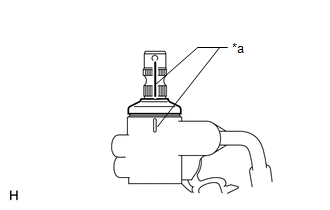
2. INSPECT TOTAL PRELOAD
|
(a) Place matchmarks as shown in the illustration. Text in Illustration
|
|
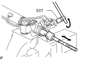
(b) Temporarily install the 2 steering rack ends to the steering rack.
NOTICE:
Do not fully turn the steering rack without the steering rack ends installed as it may damage the oil seal in the rack housing.
|
(c) Using SST, fully turn the steering rack right and left 10 times to settle it. SST: 09616-00011 |
|
|
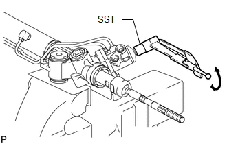
(d) Using SST, turn the control valve and measure the preload. SST: 09616-00011 Standard preload (turning): 1.6 to 2.3 N*m (16 to 23 kgf*cm, 14 to 20 in.*lbf) If the turning torque is not as specified, replace the steering gear assembly. HINT:
|
|
(e) After inspecting the preload, align the matchmarks.
 Disassembly
DISASSEMBLY
CAUTION / NOTICE / HINT
NOTICE:
When using a vise, do not overtighten it.
PROCEDURE
1. REMOVE TIE ROD END SUB-ASSEMBLY LH
(a) Put matchmarks on the tie rod end LH and stee ...
 Reassembly
REASSEMBLY
PROCEDURE
1. INSTALL STEERING RACK END SUB-ASSEMBLY
(a) Temporarily install the 2 steering rack ends to the steering rack.
(b) Fill up the ball joints of the steering rack ends with MP ...
Other materials about Toyota 4Runner:
Removal
REMOVAL
PROCEDURE
1. REMOVE FRONT WHEEL
2. REMOVE SIDE STEP ASSEMBLY LH
3. REMOVE STABILIZER CONTROL VALVE PROTECTOR
4. DRAIN SUSPENSION FLUID
5. REMOVE LOWER FRONT BUMPER COVER
6. REMOVE NO. 1 ENGINE UNDER COVER SUB-ASSEMBLY
7. REMOVE F ...
Diagnostic Trouble Code Chart
DIAGNOSTIC TROUBLE CODE CHART
HINT:
If a trouble code is output during the DTC check, inspect the trouble areas listed
for that code. For details of the code, refer to the "See page" below.
Wireless Door Lock Control System
DTC Code
...
0.0113