Toyota 4Runner: Inspection
INSPECTION
PROCEDURE
1. INSPECT FRONT POWER SEAT SWITCH LH
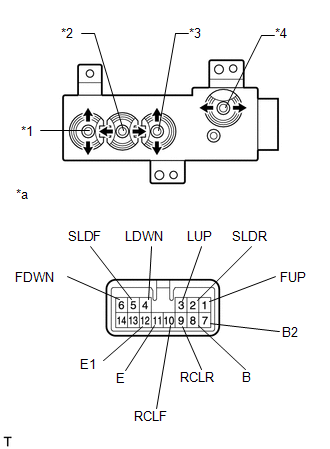
(a) Measure the resistance according to the value(s) in the table below.
Standard Resistance:
Slide Switch
|
Tester Connection |
Switch Condition |
Specified Condition |
|---|---|---|
|
5 (SLDF) - 8 (B) 5 (SLDF) - 7 (B2) |
Front |
Below 1 Ω |
|
2 (SLDR) - 11 (E) 2 (SLDR) - 12 (E1) |
||
|
5 (SLDF) - 11 (E) 5 (SLDF) - 12 (E1) |
Off |
|
|
2 (SLDR) - 11 (E) 2 (SLDR) - 12 (E1) |
||
|
5 (SLDF) - 11 (E) 5 (SLDF) - 12 (E1) |
Rear |
|
|
2 (SLDR) - 8 (B) 2 (SLDR) - 7 (B2) |
Front Vertical Switch
|
Tester Connection |
Switch Condition |
Specified Condition |
|---|---|---|
|
1 (FUP) - 8 (B) 1 (FUP) - 7 (B2) |
Up |
Below 1 Ω |
|
6 (FDWN) - 11 (E) 6 (FDWN) - 12 (E1) |
||
|
1 (FUP) - 11 (E) 1 (FUP) - 12 (E1) |
Off |
|
|
6 (FDWN) - 11 (E) 6 (FDWN) - 12 (E1) |
||
|
1 (FUP) - 11 (E) 1 (FUP) - 12 (E1) |
Down |
|
|
6 (FDWN) - 8 (B) 6 (FDWN) - 7 (B2) |
Lifter Switch
|
Tester Connection |
Switch Condition |
Specified Condition |
|---|---|---|
|
3 (LUP) - 8 (B) 3 (LUP) - 7 (B2) |
Up |
Below 1 Ω |
|
4 (LDWN) - 11 (E) 4 (LDWN) - 12 (E1) |
||
|
3 (LUP) - 11 (E) 3 (LUP) - 12 (E1) |
Off |
|
|
4 (LDWN) - 11 (E) 4 (LDWN) - 12 (E1) |
||
|
3 (LUP) - 11 (E) 3 (LUP) - 12 (E1) |
Down |
|
|
4 (LDWN) - 8 (B) 4 (LDWN) - 7 (B2) |
Reclining Switch
|
Tester Connection |
Switch Condition |
Specified Condition |
|---|---|---|
|
10 (RCLF) - 8 (B) 10 (RCLF) - 7 (B2) |
Front |
Below 1 Ω |
|
9 (RCLR) - 11 (E) 9 (RCLR) - 12 (E1) |
||
|
10 (RCLF) - 11 (E) 10 (RCLF) - 12 (E1) |
Off |
|
|
9 (RCLR) - 11 (E) 9 (RCLR) - 12 (E1) |
||
|
10 (RCLF) - 11 (E) 10 (RCLF) - 12 (E1) |
Rear |
|
|
9 (RCLR) - 8 (B) 9 (RCFR) - 7 (B2) |
If the result is not as specified, replace the front power seat switch.
Text in Illustration|
*1 |
Front Vertical Switch |
|
*2 |
Slide Switch |
|
*3 |
Lifter Switch |
|
*4 |
Reclining Switch |
|
*a |
Component without harness connected (Front Power Seat Switch) |
2. INSPECT FRONT POWER SEAT SWITCH RH
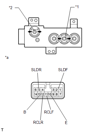
(a) Measure the resistance according to the value(s) in the table below.
Standard Resistance:
Slide Switch
|
Tester Connection |
Switch Condition |
Specified Condition |
|---|---|---|
|
2 (SLDF) - 13 (B) |
Front |
Below 1 Ω |
|
5 (SLDR) - 10 (E) |
||
|
2 (SLDF) - 10 (E) |
Off |
|
|
5 (SLDR) - 10 (E) |
||
|
2 (SLDF) - 10 (E) |
Rear |
|
|
5 (SLDR) - 13 (B) |
Reclining Switch
|
Tester Connection |
Switch Condition |
Specified Condition |
|---|---|---|
|
11 (RCLF) - 13 (B) |
Front |
Below 1 Ω |
|
12 (RCLR) - 10 (E) |
||
|
11 (RCLF) - 10 (E) |
Off |
|
|
12 (RCLR) - 10 (E) |
||
|
11 (RCLF) - 10 (E) |
Rear |
|
|
12 (RCLR) - 13 (B) |
If the result is not as specified, replace the front power seat switch.
Text in Illustration|
*1 |
Slide Switch |
|
*2 |
Reclining Switch |
|
*a |
Component without harness connected (Front Power Seat Switch) |
 Components
COMPONENTS
ILLUSTRATION
...
 Removal
REMOVAL
CAUTION / NOTICE / HINT
CAUTION:
Wear protective gloves. Sharp areas on the parts may injure your hands.
HINT:
Use the same procedure for the RH and LH sides.
The procedure li ...
Other materials about Toyota 4Runner:
A-TRAC Indicator Light does not Come ON
DESCRIPTION
The A-TRAC does not operate even if the A-TRAC switch is pressed under the following
conditions:
The TRAC or VSC system is faulty.
The temperature inside the hydraulic brake booster increases and the
A-TRAC operation is suspended ...
Removal
REMOVAL
CAUTION / NOTICE / HINT
CAUTION:
Wear protective gloves. Sharp areas on the parts may injure your hands.
PROCEDURE
1. REMOVE REAR SEAT ASSEMBLY RH
(a) Remove the rear No. 1 seat assembly RH (See page
).
2. REMOVE NO. 1 SEATBACK BOARD SUB-ASSEM ...
0.007