Toyota 4Runner: Installation
INSTALLATION
PROCEDURE
1. INSTALL CENTER CONTROL ABSORBER BRACKET LH
(a) Install the center control absorber bracket with the 2 bolts.
Torque:
29 N·m {296 kgf·cm, 21 ft·lbf}
2. INSTALL CENTER CONTROL ABSORBER BRACKET RH
HINT:
Use the same procedure described for the LH side.
3. INSTALL CENTER CONTROL ABSORBER ASSEMBLY LH
|
(a) Install the center control absorber assembly with the 3 nuts. Torque: 29 N·m {296 kgf·cm, 21 ft·lbf} |
|
.png)
|
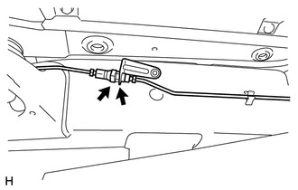
(b) Connect the tube to the 2 clamps. |
|
.png)
|
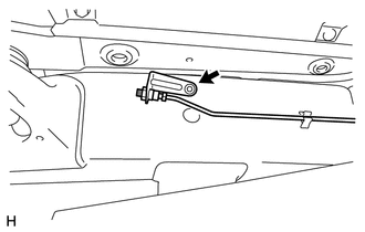
(c) Install the bracket with the bolt. Torque: 29 N·m {296 kgf·cm, 21 ft·lbf} |
|
.png)
(d) While using a wrench to hold the bracket, connect the joint.
Torque:
25 N·m {255 kgf·cm, 18 ft·lbf}
HINT:
For the joint that connects supplied parts, tighten the joint while checking the gap spacing shown in the illustration.
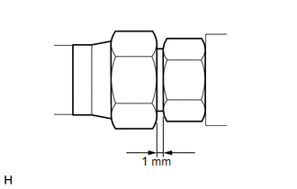
Standard clearance:
1 mm (0.0394 in.)
4. INSTALL CENTER CONTROL ABSORBER ASSEMBLY RH
HINT:
Use the same procedure described for the LH side.
5. INSTALL NO. 1 CENTER CONTROL ABSORBER TUBE LH
|
(a) Install a new No. 1 center control absorber tube with the bolt. Torque: 29 N·m {296 kgf·cm, 21 ft·lbf} |
|
(b) While using a wrench to hold the center control absorber assembly, connect the joint.
.png)
Torque:
25 N·m {255 kgf·cm, 18 ft·lbf}
HINT:
For the joint that connects supplied tubes, tighten the joint while checking the gap spacing shown in the illustration.
Standard clearance:
1 mm (0.0394 in.)
(c) Pass the center control absorber tube between the body and frame.
|
(d) Attach the 2 clamps. |
|
.png)
(e) While using a wrench to hold the bracket, connect the joint.
Torque:
25 N·m {255 kgf·cm, 18 ft·lbf}
HINT:
For the joint that connects supplied tubes, tighten the joint while checking the gap spacing shown in the illustration.
Standard clearance:
1 mm (0.0394 in.)
(f) While using a wrench to hold the bracket, connect the joint.
.png)
Torque:
25 N·m {255 kgf·cm, 18 ft·lbf}
HINT:
For the joint that connects the supplied tubes, tighten the joint while checking the gap spacing shown in the illustration.
Standard clearance:
1 mm (0.0394 in.)
6. INSTALL NO. 1 CENTER CONTROL ABSORBER TUBE RH
HINT:
Use the same procedure described for the LH side.
7. INSTALL TUBE PROTECTOR LH
|
(a) Install the tube protector LH with the bolt. Torque: 29 N·m {296 kgf·cm, 21 ft·lbf} |
|
.png)
8. INSTALL TUBE PROTECTOR RH
HINT:
Use the same procedure described for the LH side.
9. INSTALL FRONT WHEEL
.gif)
10. INSTALL REAR WHEEL
11. INSPECT FOR FLUID LEAK
 Removal
REMOVAL
CAUTION / NOTICE / HINT
NOTICE:
Be sure to read PRECAUTION before performing this procedure (See page
).
PROCEDURE
1. REMOVE FRONT WHEEL
2. REMOVE REAR WHEEL
3. REMOVE CENTER CONTROL ...
 Disposal
DISPOSAL
PROCEDURE
1. DISPOSE OF CENTER CONTROL ABSORBER ASSEMBLY LH
(a) Using a drill, make a hole in the cylinder as shown in the illustration
to discharge the gas inside.
...
Other materials about Toyota 4Runner:
Diagnosis System
DIAGNOSIS SYSTEM
1. CHECK DLC3
(a) Check the DLC3 (See page ).
2. FUNCTION OF POWER STEERING WARNING LIGHT
(a) When a malfunction is detected in the power steering system, the power steering
warning light in the combination meter comes on to inform the ...
System Description
SYSTEM DESCRIPTION
1. WIRELESS DOOR LOCK CONTROL SYSTEM DESCRIPTION
(a) This system locks/unlocks the vehicle doors remotely. The wireless control
system has the following features:
The door control receiver performs the code identification procedu ...
0.0118