Toyota 4Runner: Installation
INSTALLATION
PROCEDURE
1. INSTALL HOOD LOCK CONTROL CABLE ASSEMBLY
|
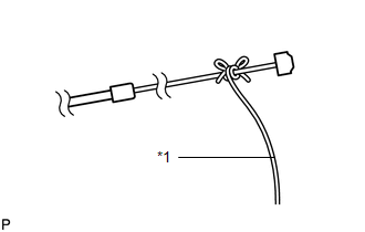
(a) Tie the string that was passed through the engine compartment to the end of the hood lock control cable assembly as shown in the illustration. Text in Illustration
|
|
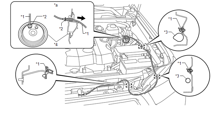
(b) Pull the string until the hood lock control cable grommet contacts the dash panel, and then connect the clamps shown in the illustration to install the hood lock control cable assembly to the engine compartment.
 Text in Illustration
|
*1 |
Hood Lock Control Cable |
*2 |
Stopper |
|
*3 |
Wire Harness |
*4 |
Grommet |
|
*a |
Engine Room Side |
- |
- |
2. INSTALL HOOD LOCK CONTROL LEVER SUB-ASSEMBLY
(a) Connect the hood lock control cable assembly.
(b) Attach the 3 claws to install the hood lock control lever sub-assembly.
|
(c) Attach the clamp. |
|
.png)
3. REMOVE AND INSTALL COWL SIDE TRIM BOARD LH
.gif)
4. INSTALL DOOR SCUFF PLATE ASSEMBLY LH
5. INSTALL HOOD LOCK ASSEMBLY
(a) Apply MP grease to the sliding areas of the hood lock assembly.
(b) Connect the hood lock control cable assembly.
(c) w/ Engine Hood Courtesy Switch:
Connect the connector.
(d) w/o Engine Hood Courtesy Switch:
Connect the connector cap.
(e) Temporary install the hood lock assembly with the 3 bolts.
(f) Adjust the hood sub-assembly (See page ).
|
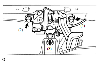
(g) Install the hood lock assembly with the 3 bolts in the order shown in the illustration. Torque: 7.5 N·m {76 kgf·cm, 66 in·lbf} |
|
6. INSTALL HOOD LOCK CONTROL CABLE COVER
|
(a) Pass the hood lock control cable assembly through the hood lock control cable cover. |
|
(b) Attach the claw to install the hood lock control cable cover.
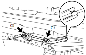
(c) Install the 2 bolts in the order shown in the illustration.
Torque:
7.5 N·m {76 kgf·cm, 66 in·lbf}
7. INSTALL LOW PITCHED HORN ASSEMBLY
8. INSTALL RADIATOR GRILLE BRACKET
9. INSTALL HIGH PITCHED HORN ASSEMBLY
10. INSTALL FRONT BUMPER COVER (w/ Intuitive Parking Assist System)
(See page )
11. INSTALL FRONT BUMPER COVER (w/o Intuitive Parking Assist System)
(See page )
 Removal
REMOVAL
PROCEDURE
1. REMOVE FRONT BUMPER COVER (w/o Intuitive Parking Assist System)
(See Page )
2. REMOVE FRONT BUMPER COVER (w/ Intuitive Parking Assist System)
(See Page )
3. REMOVE HIGH PI ...
 Hood Support
Components
COMPONENTS
ILLUSTRATION
Removal
REMOVAL
CAUTION / NOTICE / HINT
HINT:
Use the same procedure for the RH and LH sides.
The procedure listed below is for the LH side. ...
Other materials about Toyota 4Runner:
Replacement
REPLACEMENT
PROCEDURE
1. REMOVE REAR PROPELLER SHAFT ASSEMBLY
(a) for 2WD:
Remove the rear propeller shaft assembly (See page
).
(b) for 4WD:
Remove the rear propeller shaft assembly (See page
).
2. REMOVE REAR DRIVE PINION NUT
(a) Using SST and ...
Antenna Coil Open / Short (B2784)
DESCRIPTION
This DTC is stored when there is an open or short malfunction in the transponder
key amplifier coil (built into the engine switch).
DTC Code
DTC Detection Condition
Trouble Area
B2784
...
0.0273