Toyota 4Runner: Installation
INSTALLATION
PROCEDURE
1. INSTALL DOOR CONTROL SWITCH ASSEMBLY
|
(a) Attach the 2 claws to install the door control switch assembly. |
|
.png)
(b) Connect the door control switch connector.
2. INSTALL FRONT DOOR INNER GLASS WEATHERSTRIP RH
|
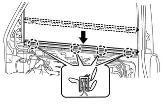
(a) Install the front door inner glass weatherstrip RH. |
|
3. INSTALL FRONT DOOR TRIM BOARD SUB-ASSEMBLY RH
|
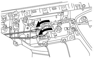
(a) Connect the front door lock remote control cable assembly and front door inside locking cable assembly. |
|
|
(b) Connect the connector. |
|
.png)
|
(c) Attach the front door trim board sub-assembly to the 4 claws of the front door inner glass as shown in the illustration. |
|
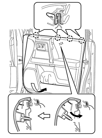
(d) Attach the 11 clips to install the front door trim board sub-assembly RH.
(e) Install the 3 screws.
(f) Attach the 4 claws to install the 2 door armrest caps.
4. INSTALL DOOR NO. 2 INSIDE HANDLE BEZEL RH
(a) Attach the 3 claws to install the No.2 inside handle bezel RH.
5. INSTALL FRONT DOOR LOWER FRAME BRACKET GARNISH RH
(a) Attach the 2 clips to install the front door lower frame bracket garnish RH.
 Removal
REMOVAL
PROCEDURE
1. REMOVE FRONT DOOR LOWER FRAME BRACKET GARNISH RH
(a) Detach the 2 clips and remove the front door lower frame bracket
garnish RH.
...
 Door Control Transmitter(w/ Smart Key System)
Components
COMPONENTS
ILLUSTRATION
Removal
REMOVAL
CAUTION / NOTICE / HINT
NOTICE:
Take extra care when handling these precision electronic components.
PROCEDURE
1. REMOVE TRANSMITTER B ...
Other materials about Toyota 4Runner:
How To Proceed With Troubleshooting
CAUTION / NOTICE / HINT
HINT:
*: Use the Techstream.
PROCEDURE
1.
VEHICLE BROUGHT TO WORKSHOP
NEXT
2.
INSPECT BATTERY VOLTAGE
...
Removal
REMOVAL
CAUTION / NOTICE / HINT
NOTICE:
Make sure to release the vacuum from the brake booster before removing the master
cylinder from the brake booster.
PROCEDURE
1. DRAIN BRAKE FLUID
NOTICE:
Wash off brake fluid immediately if it comes in contact w ...
0.0094