Toyota 4Runner: Installation
INSTALLATION
CAUTION / NOTICE / HINT
CAUTION:
Wear protective gloves. Sharp areas on the parts may injure your hands.
PROCEDURE
1. INSTALL REAR NO. 1 SEAT OUTER BELT ASSEMBLY RH
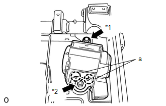
NOTICE:
When installing the retractor, make sure the claws of the vehicle (labeled "a" in the illustration) only contact the installation areas of the retractor.
(a) Align the claws with the seat belt positioning holes and install the retractor of the seat belt with the nut and bolt as shown in the illustration.
HINT:
First install the bolt, and then install the nut.
Torque:
for bolt :
7.5 N·m {76 kgf·cm, 66 in·lbf}
for nut :
42 N·m {428 kgf·cm, 31 ft·lbf}
Text in Illustration|
*1 |
Bolt |
|
*2 |
Nut |
2. INSTALL REAR SEAT SHOULDER BELT GUIDE
.gif)
3. INSTALL REAR SEATBACK EDGE PROTECTOR
4. INSTALL SEATBACK COVER WITH PAD
5. INSTALL REAR SEAT LOCK STRIKER
6. INSTALL REAR SEATBACK LOCK STRIKER PROTECTOR
7. INSTALL REAR SEAT SHOULDER BELT COVER
8. INSTALL SEAT BELT ANCHOR COVER CAP
9. INSTALL REAR NO. 1 SEAT HEADREST SUPPORT ASSEMBLY
10. INSTALL REAR SEATBACK STOP BUTTON GROMMET
11. INSTALL REAR SEATBACK LOCK ASSEMBLY RH
12. INSTALL REAR SEATBACK LOCK COVER RH
13. INSTALL CENTER NO. 2 SEATBACK COVER
14. INSTALL CENTER SEATBACK ASSEMBLY
15. INSTALL CENTER SEATBACK COVER SUB-ASSEMBLY
16. INSTALL REAR SEAT CENTER INNER BELT ASSEMBLY
17. INSTALL REAR SEAT INNER RECLINING COVER RH
18. INSTALL NO. 1 SEATBACK BOARD SUB-ASSEMBLY (for Plastic Seatback Board)
19. INSTALL NO. 1 SEATBACK BOARD SUB-ASSEMBLY (for Seatback Board with Carpet)
20. INSTALL REAR SEAT ASSEMBLY RH
(a) Install the rear No. 2 seat assembly RH (See page
).
 Inspection
INSPECTION
PROCEDURE
1. INSPECT REAR NO. 1 SEAT OUTER BELT ASSEMBLY RH
NOTICE:
Do not disassemble the retractor.
(a) When the inclination of the retractor is 15° or less, check that the belt
...

Other materials about Toyota 4Runner:
Cursor or Map Rotates when Vehicle Stopped
PROCEDURE
1.
CHECK CONDITION
(a) Check with the customer if the vehicle has been turned by a turntable.
OK:
Vehicle has not been turned by a turntable.
HINT:
If the vehicle is turned on a turntable with ...
Transfer Case Front Oil Seal
Components
COMPONENTS
ILLUSTRATION
Replacement
REPLACEMENT
PROCEDURE
1. DRAIN TRANSFER OIL
2. REMOVE FRONT PROPELLER SHAFT ASSEMBLY
(a) Remove the front propeller shaft (See page
).
3. REMOVE FRONT OUTPUT SHAFT COMPANION FLANGE SUB-ASSEMBLY ...
0.0065