Toyota 4Runner: Installation
INSTALLATION
PROCEDURE
1. INSTALL INDOOR NO. 2 ELECTRICAL KEY ANTENNA ASSEMBLY
|
(a) Attach the 2 claws to install the indoor No. 2 electrical key antenna. |
|
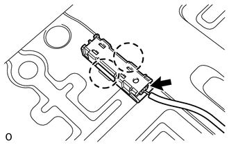
(b) Connect the connector.
2. INSTALL NO. 1 LUGGAGE COMPARTMENT TRIM COVER
.gif)
3. INSTALL REAR FLOOR PAD (w/o Deck Board)
(a) Install the rear floor pad.
4. INSTALL REAR FLOOR CARPET ASSEMBLY (w/o Deck Board)
5. INSTALL REAR FLOOR CARPET ASSEMBLY (w/ Deck Board)
(a) Attach the 4 claws to install the rear floor carpet.
6. INSTALL REAR FLOOR MAT REAR SUPPORT PLATE
7. INSTALL INNER FLOOR SIDE RAIL SUB-ASSEMBLY (w/ Deck Board)
8. INSTALL DECK BOARD ASSEMBLY (w/ Deck Board)
9. INSTALL LUGGAGE COMPARTMENT SIDE COVER SUB-ASSEMBLY LH (w/ Deck Board)
10. INSTALL LUGGAGE COMPARTMENT SIDE COVER SUB-ASSEMBLY RH (w/ Deck Board)
11. INSTALL REAR NO. 2 FLOOR BOARD ASSEMBLY (w/ Deck Board)
12. INSTALL NO. 2 DECK BOARD SUB-ASSEMBLY (w/o Deck Board)
13. INSTALL NO. 2 LUGGAGE COMPARTMENT TRIM COVER (w/ Deck Board, w/o Rear No. 2 Seat)
14. INSTALL NO. 1 DECK BOARD SUB-ASSEMBLY (w/o Deck Board)
15. INSTALL NO. 1 LUGGAGE COMPARTMENT TRIM COVER (w/o Deck Board)
16. INSTALL REAR NO. 2 SEAT ASSEMBLY (w/ Rear No. 2 Seat)
(a) Install the rear No. 2 seat assembly (See page
).
 Components
COMPONENTS
ILLUSTRATION
ILLUSTRATION
ILLUSTRATION
...
 Removal
REMOVAL
PROCEDURE
1. REMOVE REAR NO. 2 SEAT ASSEMBLY
(a) Remove the rear No. 2 seat assembly (See page
).
2. REMOVE NO. 1 LUGGAGE COMPARTMENT TRIM COVER (w/o Deck Board)
3. REMOVE NO. 1 DECK ...
Other materials about Toyota 4Runner:
Reassembly
REASSEMBLY
CAUTION / NOTICE / HINT
CAUTION:
Wear protective gloves. Sharp areas on the parts may injure your hands.
HINT:
Use the same procedure for the RH and LH sides.
The procedure listed below is for the LH side.
PROCEDURE
1. INSTA ...
Installation
INSTALLATION
PROCEDURE
1. INSTALL TRANSMISSION VALVE BODY ASSEMBLY
(a) Install the spring and check ball body.
(b) Insert the pin of the manual valve into the hole of the manual valve
lever.
Text in Illustration
*1
...
0.0143