Toyota 4Runner: Installation
INSTALLATION
PROCEDURE
1. INSTALL BRAKE PEDAL SUPPORT ASSEMBLY
(a) Temporarily install the set bolt.
(b) Install the brake booster assembly (See page
.gif) ).
).
(c) Install the brake master cylinder sub-assembly (See page
).
(d) Install the brake pedal support assembly with the 4 nuts.
Torque:
14 N·m {145 kgf·cm, 10 ft·lbf}
(e) Install the brake pedal support reinforcement set bolt.
Torque:
20 N·m {204 kgf·cm, 15 ft·lbf}
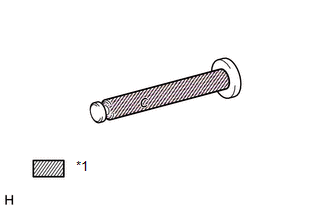
2. INSTALL PUSH ROD PIN
|
(a) Apply a light coat of lithium soap base glycol grease to the inner surface of the hole on the brake pedal lever. Text in Illustration
|
|
|
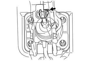
(b) Set the master cylinder push rod clevis in place, insert the push rod pin from the left side of the vehicle and then install a new clip. |
|
3. INSTALL BRAKE PEDAL RETURN SPRING
(a) Apply a light coat of lithium soap base glycol grease to the inner surface of the hole on the brake pedal support assembly.
(b) Install the brake pedal return spring to the brake pedal support assembly.
4. CONNECT BRAKE PEDAL LOAD SENSING SWITCH
(a) Connect the brake pedal load sensing switch connector.
5. INSTALL STOP LIGHT SWITCH ASSEMBLY
(a) Install the stop light switch assembly (See page
).
(b) Connect the stop light switch connector.
6. INSTALL LOWER NO. 1 INSTRUMENT PANEL AIRBAG ASSEMBLY
(a) Install the lower No. 1 instrument panel airbag assembly (See page
).
7. CONNECT CABLE TO NEGATIVE BATTERY TERMINAL
NOTICE:
When disconnecting the cable, some systems need to be initialized after the cable
is reconnected (See page ).
8. BLEED BRAKE SYSTEM
9. CHECK AND ADJUST BRAKE PEDAL
(a) Check and adjust brake pedal (See page ).
 Reassembly
REASSEMBLY
PROCEDURE
1. INSTALL STOP LIGHT SWITCH MOUNTING ADJUSTER
(a) Install a new stop light switch mounting adjuster to the brake pedal support
assembly.
2. INSTALL BRAKE PEDAL PAD
(a) Ins ...
 Brake System
...
Other materials about Toyota 4Runner:
Door Side Airbag Sensor RH Initialization Incomplete (B1693/81,B1698/82)
DESCRIPTION
The circuit for the side collision sensor LH or RH (to determine deployment of
the front seat side airbag LH or RH and curtain shield airbag LH or RH) is composed
of the center airbag sensor, rear airbag sensor LH or RH and side airbag sensor ...
Rear differential lock system
The rear differential lock system is provided for use only when wheel
spinning occurs in a ditch or on a slippery or rugged surface.
The rear differential lock system is effective in case one of the rear wheels
is spinning.
Press the switch to lock the ...
0.0139