Toyota 4Runner: Integration Relay
On-vehicle Inspection
ON-VEHICLE INSPECTION
PROCEDURE
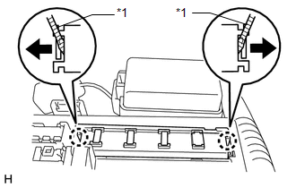
1. REMOVE NO. 1 RELAY BLOCK COVER
(a) Remove the No. 1 relay block cover.
2. INSPECT NO. 1 INTEGRATION RELAY
|
(a) Using a screwdriver, detach the 2 claws and disconnect the No. 1 integration relay from the engine room junction block. HINT: Tape the screwdriver tip before use. Text in Illustration
|
|
|
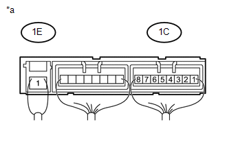
(b) Measure the resistance according to the value(s) in the table below. Standard Resistance:
If the result is not as specified, replace the No. 1 integration relay. Text in Illustration
|
|
(c) Attach the 2 claws to install the No. 1 integration relay to the engine room junction block.
3. INSTALL NO. 1 RELAY BLOCK COVER
(a) Install the No. 1 relay block cover.
 Horn System
Parts Location
PARTS LOCATION
ILLUSTRATION
Problem Symptoms Table
PROBLEM SYMPTOMS TABLE
HINT:
Use the table below to help determine the cause of problem symptoms. If multiple
suspected ...
 Lighting (ext)
...
Other materials about Toyota 4Runner:
Diagnostic Trouble Code Chart
DIAGNOSTIC TROUBLE CODE CHART
HINT:
If a trouble code is output during the DTC check, inspect the trouble areas listed
for that code. For details of the code, refer to the "See page" below.
Steering Lock System
DTC Code
De ...
Diagnosis System
DIAGNOSIS SYSTEM
1. CHECK WARNING LIGHT
NOTICE:
When there is a problem with the tire pressure warning system, the tire
pressure warning light blinks at 0.5 second intervals and comes on after
1 minute.
When the malfunction has been corr ...
0.0067