Toyota 4Runner: Inverter Main Switch
Components
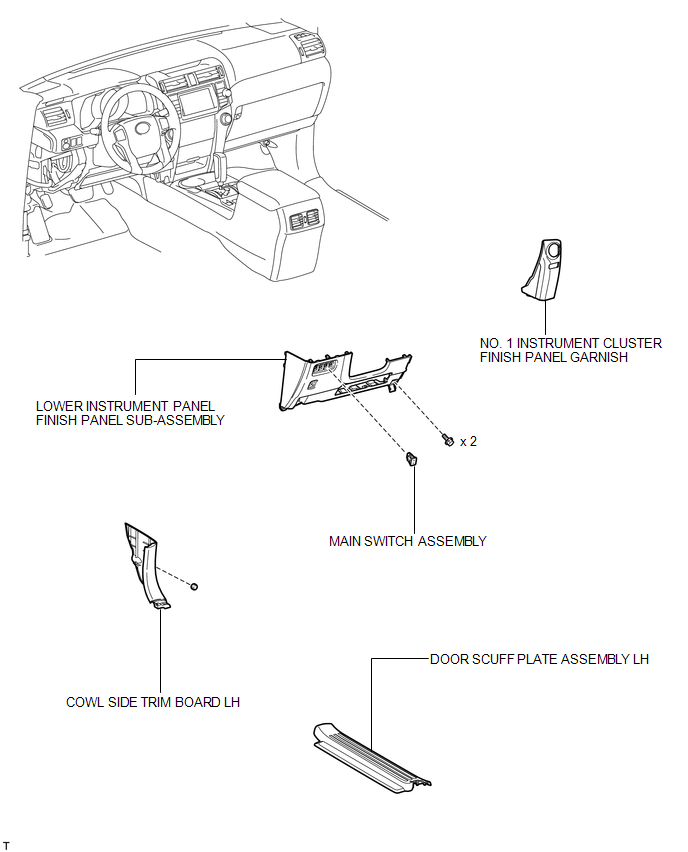
COMPONENTS
ILLUSTRATION
Installation
INSTALLATION
PROCEDURE
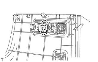
1. INSTALL MAIN SWITCH ASSEMBLY
(a) Attach the 2 claws to install the main switch.
2. INSTALL LOWER INSTRUMENT PANEL FINISH PANEL SUB-ASSEMBLY
.gif)
3. INSTALL COWL SIDE TRIM BOARD LH
4. INSTALL DOOR SCUFF PLATE ASSEMBLY LH
5. INSTALL NO. 1 INSTRUMENT CLUSTER FINISH PANEL GARNISH
Removal
REMOVAL
PROCEDURE
1. REMOVE NO. 1 INSTRUMENT CLUSTER FINISH PANEL GARNISH
.gif)
2. REMOVE DOOR SCUFF PLATE ASSEMBLY LH
3. REMOVE COWL SIDE TRIM BOARD LH
4. REMOVE LOWER INSTRUMENT PANEL FINISH PANEL SUB-ASSEMBLY
5. REMOVE MAIN SWITCH ASSEMBLY
|
(a) Detach the 2 claws and remove the main switch. |
|
 Removal
REMOVAL
PROCEDURE
1. REMOVE NO. 1 INSTRUMENT CLUSTER FINISH PANEL GARNISH
2. REMOVE NO. 2 INSTRUMENT CLUSTER FINISH PANEL GARNISH
3. REMOVE FRONT NO. 1 CONSOLE BOX INSERT
4. REMOVE FRONT ...

Other materials about Toyota 4Runner:
Precaution
PRECAUTION
1. EXPRESSIONS OF IGNITION SWITCH
The type of ignition switch used on this model differs according to the specifications
of the vehicle.
The expressions listed in the table below are used in this section.
Expression
Ignit ...
Wireless remote control/electronic key battery
Replace the battery with a new one if it is depleted.
You will need the following items:
• Flathead screwdriver
• Lithium battery CR2016 (vehicles without a smart key system), or CR1632
(vehicles with a smart key system)
Replacing the battery (vehic ...
0.0065