Toyota 4Runner: Lost Communication with A/C ECU (U0164)
DESCRIPTION
|
DTC Code |
DTC Detection Condition |
Trouble Area |
|---|---|---|
|
U0164 |
There is no communication from the air conditioning amplifier assembly. |
|
HINT:
For vehicles with a smart key system only.
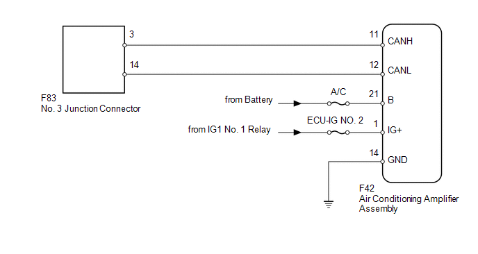
WIRING DIAGRAM
CAUTION / NOTICE / HINT
NOTICE:
Inspect the fuses for circuits related to this system before performing the following inspection procedure.
HINT:
Operating the ignition switch, any switches or any doors triggers related ECU and sensor communication with the CAN, which causes resistance variation.
PROCEDURE
|
1. |
DISCONNECT CABLE FROM NEGATIVE BATTERY TERMINAL |
(a) Disconnect the cable from the negative (-) battery terminal before measuring the resistances of the main wire and branch wire.
CAUTION:
Wait at least 90 seconds after disconnecting the cable from the negative (-) battery terminal to disable the SRS system.
NOTICE:
When disconnecting the cable, some systems need to be initialized after the cable
is reconnected (See page .gif) ).
).
|
.gif)
|
2. |
CHECK FOR OPEN IN CAN BUS WIRE (AIR CONDITIONING AMPLIFIER ASSEMBLY BRANCH WIRE) |
|
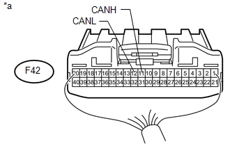
(a) Disconnect the F42 air conditioning amplifier assembly connector. |
|
(b) Measure the resistance according to the value(s) in the table below.
Standard Resistance:
|
Tester Connection |
Switch Condition |
Specified Condition |
|---|---|---|
|
F42-11 (CANH) - F42-12 (CANL) |
Ignition switch off |
54 to 64 Ω |
|
*a |
Rear view of wire harness connector (to Air Conditioning Amplifier Assembly) |
| NG | .gif) |
REPAIR OR REPLACE AIR CONDITIONING AMPLIFIER ASSEMBLY BRANCH WIRE OR CONNECTOR (CANH, CANL) |
|
|
3. |
CHECK HARNESS AND CONNECTOR (AIR CONDITIONING AMPLIFIER ASSEMBLY - BATTERY AND BODY GROUND) |
|
(a) Connect the cable to the negative (-) battery terminal. NOTICE: When disconnecting the cable, some systems need to be initialized after
the cable is reconnected (See page |
|
(b) Measure the resistance according to the value(s) in the table below.
Standard Resistance:
|
Tester Connection |
Condition |
Specified Condition |
|---|---|---|
|
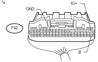
F42-14 (GND) - Body ground |
Always |
Below 1 Ω |
(c) Measure the voltage according to the value(s) in the table below.
Standard Voltage:
|
Tester Connection |
Switch Condition |
Specified Condition |
|---|---|---|
|
F42-21 (B) - Body ground |
Always |
11 to 14 V |
|
F42-1 (IG+) - Body ground |
Ignition switch ON |
11 to 14 V |
|
*a |
Rear view of wire harness connector (to Air Conditioning Amplifier Assembly) |
| OK | |
REPLACE AIR CONDITIONING AMPLIFIER ASSEMBLY |
| NG | |
REPAIR OR REPLACE HARNESS OR CONNECTOR |
 Lost Communication with "Seat Control Module A" (U0208)
DESCRIPTION
DTC Code
DTC Detection Condition
Trouble Area
U0208
There is no communication from the front power seat switch LH.
...
 Brake Actuator (Skid Control ECU) Communication Stop Mode
DESCRIPTION
Detection Item
Symptom
Trouble Area
Brake Actuator (Skid Control ECU) Communication Stop Mode
Either condition is met:
...
Other materials about Toyota 4Runner:
Driver Side Power Window does not Operate with Power Window Master Switch
DESCRIPTION
If the manual up/down function does not operate, there may be a malfunction
in the multiplex network master switch, power window regulator motor, harness
or connector.
WIRING DIAGRAM
CAUTION / NOTICE / HINT
NOTICE:
Inspe ...
Removal
REMOVAL
PROCEDURE
1. DRAIN ENGINE COOLANT
(a) Drain engine coolant (See page ).
2. REMOVE RADIATOR ASSEMBLY
(a) Remove the radiator assembly (See page ).
3. RECOVER REFRIGERANT FROM REFRIGERATION SYSTEM
4. DISCONNECT DISCHARGE HOSE SUB-ASSEMBLY
...
0.0069