Toyota 4Runner: Lost Communication with Gateway Module (Power Management2) (U1002)
DESCRIPTION
- The power management control ECU stores this DTC when no signals can be received from the ECUs that are memorized as those connected to the power management bus.
- When the power management control ECU receives a response signal from the ECUs connected to the power management bus, the power management ECU recognizes and memorizes that the ECU is connected to the power management bus. Based on this memorized data, the power management control ECU monitors for malfunctions in the ECUs connected to the power management bus when communicating with those ECUs. If the power management control ECU cannot receive response signals from the ECUs that are memorized as those connected to the power management bus, the power management control ECU determines that a malfunction exists.
- If 2 or more DTCs are output during the DTC check, one side of the CAN branch wire may be open (one side of the CANH [branch wire]/CANL [branch wire] of the ECU and/or sensor is open).
|
DTC Code |
DTC Detection Condition |
Trouble Area |
|---|---|---|
|
U1002 |
Lost communication with the gateway module (Power Management2). |
|
HINT:
For vehicles with a smart key system only.
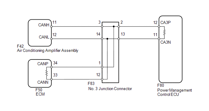
WIRING DIAGRAM
CAUTION / NOTICE / HINT
NOTICE:
Inspect the fuses for circuits related to this system before performing the following inspection procedure.
HINT:
Operating the ignition switch, any switches or any doors triggers related ECU and sensor communication with the CAN, which causes resistance variation.
PROCEDURE
|
1. |
DISCONNECT CABLE FROM NEGATIVE BATTERY TERMINAL |
(a) Disconnect the cable from the negative (-) battery terminal before measuring the resistances of the main wire and branch wire.
CAUTION:
Wait at least 90 seconds after disconnecting the cable from the negative (-) battery terminal to disable the SRS system.
NOTICE:
When disconnecting the cable, some systems need to be initialized after the cable
is reconnected (See page .gif) ).
).
|
.gif)
|
2. |
CHECK FOR CAN BUS WIRE (MAIN WIRE FOR DISCONNECTION, BUS LINE FOR SHORT CIRCUIT) |
|
(a) Measure the resistance according to the value(s) in the table below. Standard Resistance:
|
|
| B | .gif) |
GO TO STEP 9 |
| C | |
GO TO STEP 18 |
|
|
3. |
CHECK FOR OPEN IN CAN BUS MAIN WIRE (NO. 3 JUNCTION CONNECTOR - ECM) |
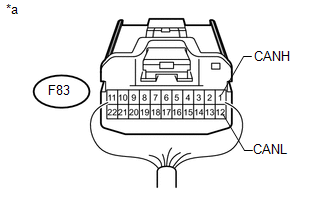
(a) Disconnect the F83 No. 3 junction connector connector.
(b) Measure the resistance according to the value(s) in the table below.
Standard Resistance:
|
Tester Connection |
Switch Condition |
Specified Condition |
|---|---|---|
|
F83-1 (CANH) - F83-12 (CANL) |
Ignition switch off |
108 to 132 Ω |
|
*a |
Rear view of wire harness connector (to No. 3 Junction Connector) |
| NG | |
GO TO STEP 5 |
|
|
4. |
CHECK FOR OPEN IN CAN BUS MAIN WIRE (NO. 3 JUNCTION CONNECTOR - POWER MANAGEMENT CONTROL ECU) |
|
(a) Measure the resistance according to the value(s) in the table below. Standard Resistance:
|
|
| OK | |
REPAIR OR REPLACE NO. 3 JUNCTION CONNECTOR |
| NG | |
GO TO STEP 7 |
|
5. |
CONNECT CONNECTOR |
(a) Reconnect the F83 No. 3 junction connector connector.
|
|
6. |
CHECK FOR OPEN IN CAN BUS MAIN WIRE (ECM - NO. 3 JUNCTION CONNECTOR) |
|
(a) Disconnect the F50 ECM connector. |
|
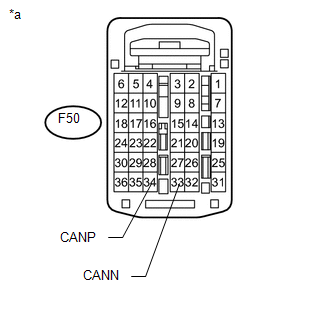
(b) Measure the resistance according to the value(s) in the table below.
Standard Resistance:
|
Tester Connection |
Switch Condition |
Specified Condition |
|---|---|---|
|
F50-34 (CANP) - F50-33 (CANN) |
Ignition switch off |
108 to 132 Ω |
|
*a |
Rear view of wire harness connector (to ECM) |
| OK | |
REPLACE ECM |
| NG | |
REPAIR OR REPLACE CAN MAIN WIRE CONNECTED TO ECM (ECM - NO. 3 JUNCTION CONNECTOR) |
|
7. |
CONNECT CONNECTOR |
(a) Reconnect the F83 No. 3 junction connector connector.
|
|
8. |
CHECK FOR OPEN IN CAN BUS MAIN WIRE (POWER MANAGEMENT CONTROL ECU - NO. 3 JUNCTION CONNECTOR) |
|
(a) Disconnect the F80 power management control ECU connector. |
|
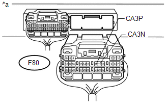
(b) Measure the resistance according to the value(s) in the table below.
Standard Resistance:
|
Tester Connection |
Switch Condition |
Specified Condition |
|---|---|---|
|
F80-12 (CA3P) - F80-11 (CA3N) |
Ignition switch off |
108 to 132 Ω |
|
*a |
Rear view of wire harness connector (to Power Management Control ECU) |
| OK | |
REPLACE POWER MANAGEMENT CONTROL ECU |
| NG | |
REPAIR OR REPLACE CAN MAIN WIRE CONNECTED TO POWER MANAGEMENT CONTROL ECU (POWER MANAGEMENT CONTROL ECU - NO. 3 JUNCTION CONNECTOR) |
|
9. |
CHECK FOR SHORT IN CAN BUS WIRES (NO. 3 JUNCTION CONNECTOR - AIR CONDITIONING AMPLIFIER ASSEMBLY) |
|
(a) Disconnect the F83 No. 3 junction connector connector. |
|
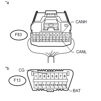
(b) Measure the resistance according to the value(s) in the table below.
Standard Resistance:
|
Tester Connection |
Switch Condition |
Specified Condition |
|---|---|---|
|
F83-3 (CANH) - F83-14 (CANL) |
Ignition switch off |
200 Ω or higher |
|
F83-3 (CANH) - F13-4 (CG) |
Ignition switch off |
200 Ω or higher |
|
F83-14 (CANL) - F13-4 (CG) |
Ignition switch off |
200 Ω or higher |
|
F83-3 (CANH) - F13-16 (BAT) |
Ignition switch off |
6 kΩ or higher |
|
F83-14 (CANL) - F13-16 (BAT) |
Ignition switch off |
6 kΩ or higher |
|
*a |
Rear view of wire harness connector (to No. 3 Junction Connector) |
|
*b |
Front view of DLC3 |
| NG | |
GO TO STEP 12 |
|
|
10. |
CHECK FOR SHORT IN CAN BUS WIRES (NO. 3 JUNCTION CONNECTOR - ECM) |
|
(a) Measure the resistance according to the value(s) in the table below. Standard Resistance:
|
|

| NG | |
GO TO STEP 14 |
|
|
11. |
CHECK FOR SHORT IN CAN BUS WIRES (NO. 3 JUNCTION CONNECTOR - POWER MANAGEMENT CONTROL ECU) |
|
(a) Measure the resistance according to the value(s) in the table below. Standard Resistance:
|
|
| OK | |
REPAIR OR REPLACE NO. 3 JUNCTION CONNECTOR |
| NG | |
GO TO STEP 16 |
|
12. |
CONNECT CONNECTOR |
(a) Reconnect the F83 No. 3 junction connector connector.
|
|
13. |
CHECK FOR SHORT IN CAN BUS WIRES (AIR CONDITIONING AMPLIFIER ASSEMBLY) |
|
(a) Disconnect the F42 air conditioning amplifier assembly connector. |
|
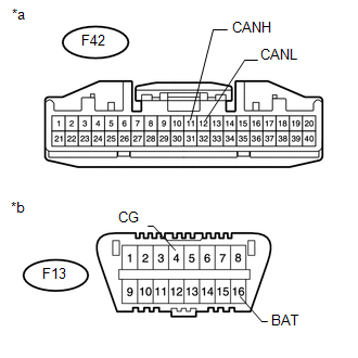
(b) Measure the resistance according to the value(s) in the table below.
Standard Resistance:
|
Tester Connection |
Switch Condition |
Specified Condition |
|---|---|---|
|
F42-11 (CANH) - F42-12 (CANL) |
Ignition switch off |
54 to 69 Ω |
|
F42-11 (CANH) - F13-4 (CG) |
Ignition switch off |
200 Ω or higher |
|
F42-12 (CANL) - F13-4 (CG) |
Ignition switch off |
200 Ω or higher |
|
F42-11 (CANH) - F13-16 (BAT) |
Ignition switch off |
6 kΩ or higher |
|
F42-12 (CANL) - F13-16 (BAT) |
Ignition switch off |
6 kΩ or higher |
|
*a |
Front view of wire harness connector (to Air Conditioning Amplifier Assembly) |
|
*b |
Front view of DLC3 |
| OK | |
REPLACE AIR CONDITIONING AMPLIFIER ASSEMBLY |
| NG | |
REPAIR OR REPLACE AIR CONDITIONING AMPLIFIER ASSEMBLY BRANCH WIRE OR CONNECTOR (CANH, CANL) |
|
14. |
CONNECT CONNECTOR |
(a) Reconnect the F83 No. 3 junction connector connector.
|
|
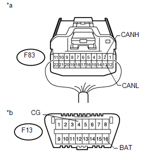
15. |
CHECK FOR SHORT IN CAN BUS WIRES (ECM) |
(a) Disconnect the F50 ECM connector.
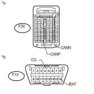
(b) Measure the resistance according to the value(s) in the table below.
Standard Resistance:
|
Tester Connection |
Switch Condition |
Specified Condition |
|---|---|---|
|
F50-34 (CANP) - F50-33 (CANN) |
Ignition switch off |
108 to 132 Ω |
|
F50-34 (CANP) - F13-4 (CG) |
Ignition switch off |
200 Ω or higher |
|
F50-33 (CANN) - F13-4 (CG) |
Ignition switch off |
200 Ω or higher |
|
F50-34 (CANP) - F13-16 (BAT) |
Ignition switch off |
6 kΩ or higher |
|
F50-33 (CANN) - F13-16 (BAT) |
Ignition switch off |
6 kΩ or higher |
|
*a |
Rear view of wire harness connector (to ECM) |
|
*b |
Front view of DLC3 |
| OK | |
REPLACE ECM |
| NG | |
REPAIR OR REPLACE ECM MAIN WIRE OR CONNECTOR (CANP, CANN) |
|
16. |
CONNECT CONNECTOR |
(a) Reconnect the F83 No. 3 junction connector connector.
|
|
17. |
CHECK FOR SHORT IN CAN BUS WIRES (POWER MANAGEMENT CONTROL ECU) |
|
(a) Disconnect the F80 power management control ECU connector. |
|
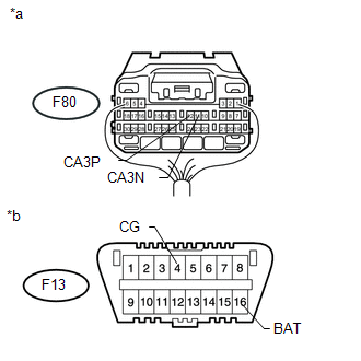
(b) Measure the resistance according to the value(s) in the table below.
Standard Resistance:
|
Tester Connection |
Switch Condition |
Specified Condition |
|---|---|---|
|
F80-12 (CA3P) - F80-11 (CA3N) |
Ignition switch off |
108 to 132 Ω |
|
F80-12 (CA3P) - F13-4 (CG) |
Ignition switch off |
200 Ω or higher |
|
F80-11 (CA3N) - F13-4 (CG) |
Ignition switch off |
200 Ω or higher |
|
F80-12 (CA3P) - F13-16 (BAT) |
Ignition switch off |
6 kΩ or higher |
|
F80-11 (CA3N) - F13-16 (BAT) |
Ignition switch off |
6 kΩ or higher |
|
*a |
Rear view of wire harness connector (to Power Management Control ECU) |
|
*b |
Front view of DLC3 |
| OK | |
REPLACE POWER MANAGEMENT CONTROL ECU |
| NG | |
REPAIR OR REPLACE POWER MANAGEMENT CONTROL ECU MAIN WIRE OR CONNECTOR (CA3P, CA3N) |
|
18. |
CHECK HARNESS AND CONNECTOR (POWER MANAGEMENT CONTROL ECU - BATTERY AND GROUND) |
|
(a) Connect the cable to the negative (-) battery terminal. NOTICE: When disconnecting the cable, some systems need to be initialized after
the cable is reconnected (See page |
|
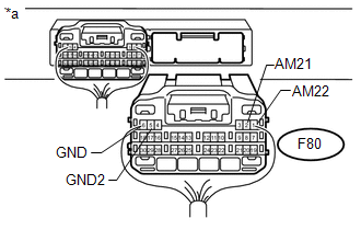
(b) Disconnect the F80 power management control ECU connector.
(c) Measure the resistance according to the value(s) in the table below.
Standard Resistance:
|
Tester Connection |
Condition |
Specified Condition |
|---|---|---|
|
F80-5 (GND2) - Body ground |
Always |
Below 1 Ω |
|
F80-6 (GND) - Body ground |
Always |
Below 1 Ω |
(d) Measure the voltage according to the value(s) in the table below.
Standard Voltage:
|
Tester Connection |
Condition |
Specified Condition |
|---|---|---|
|
F80-1 (AM22) - Body ground |
Always |
11 to 14 V |
|
F80-2 (AM21) - Body ground |
Always |
11 to 14 V |
|
*a |
Rear view of wire harness connector (to Power Management Control ECU) |
| OK | |
REPLACE POWER MANAGEMENT CONTROL ECU |
| NG | |
REPAIR OR REPLACE HARNESS OR CONNECTOR |
 Diagnostic Trouble Code Chart
DIAGNOSTIC TROUBLE CODE CHART
HINT:
If a trouble code is output during the DTC check, inspect the trouble areas listed
for that code. For details of code, refer to the "See page" below.
...
 Lost Communication with Gateway Module (MS Bus) (U1002,U1114)
DESCRIPTION
The main body ECU (multiplex network body ECU) stores this DTC when
no signals can be received from the ECUs that are memorized as those connected
to the CAN MS bus.
Wh ...
Other materials about Toyota 4Runner:
Data List / Active Test
DATA LIST / ACTIVE TEST
1. READ DATA LIST
HINT:
Using the Techstream to read the Data List allows the values or states of switches,
sensors, actuators and other items to be read without removing any parts. This non-intrusive
inspection can be very usefu ...
How To Proceed With Troubleshooting
CAUTION / NOTICE / HINT
HINT:
Use these procedures to troubleshoot the push-button start function.
*: Use the Techstream.
PROCEDURE
1.
VEHICLE BROUGHT TO WORKSHOP
NEXT
...
0.0067