Toyota 4Runner: Manual (SOS) Switch Red Indicator Malfunction (B1570)
DESCRIPTION
This DTC is stored when the DCM (Telematics Transceiver) detects an open or short in the manual (SOS) switch red indicator circuit of the manual (SOS) switch.
The manual (SOS) switch red indicator illuminates for 2 seconds and goes off when the ignition switch is turned to ON. If a malfunction in the Safety Connect is detected, the manual (SOS) switch red indicator will illuminate.
However, the manual (SOS) switch red indicator may not illuminate when this DTC is stored.
HINT:
The manual (SOS) switch red indicator will not operate to indicate another DTC is set, therefore a voice guidance will be heard.
|
DTC Code |
DTC Detection Condition |
Trouble Area |
|---|---|---|
|
B1570 |
Current for the manual (SOS) switch red indicator reaches the malfunction criteria for 10 seconds when the ignition switch is ON. |
|
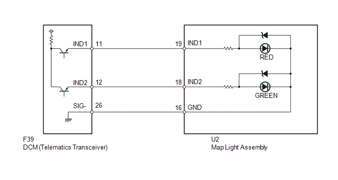
WIRING DIAGRAM
PROCEDURE
|
1. |
CHECK FOR DTC |
(a) Turn the ignition switch off.
(b) Connect the Techstream to the DLC3.
(c) Turn the ignition switch to ON and wait for 10 seconds.
(d) Perform "Health Check" and check for current DTCs (See page
.gif) ).
).
Result
|
Result |
Proceed to |
|---|---|
|
DTC B1570 and B1571 are output |
A |
|
DTC B1570 is output (DTC B1571 is not output) |
B |
| B | .gif) |
GO TO STEP 5 |
|
.gif)
|
2. |
CHECK HARNESS AND CONNECTOR (DCM - MAP LIGHT) |
|
(a) Disconnect the F39 DCM (Telematics Transceiver) connector. |
|
(b) Disconnect the U2 map light assembly connector.
(c) Measure the resistance according to the value(s) in the table below.
Standard Resistance:
|
Tester Connection |
Condition |
Specified Condition |
|---|---|---|
|
F39-11 (IND1) - U2-19 (IND1) |
Always |
Below 1 Ω |
|
F39-12 (IND2) - U2-18 (IND2) |
Always |
Below 1 Ω |
|
F39-26 (SIG-) - U2-16 (GND) |
Always |
Below 1 Ω |
|
F39-11 (IND1) - Body ground |
Always |
10 kΩ or higher |
|
F39-12 (IND2) - Body ground |
Always |
10 kΩ or higher |
|
F39-26 (SIG-) - Body ground |
Always |
10 kΩ or higher |
|
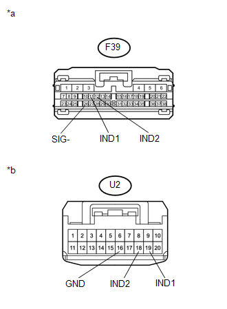
*a |
Front view of wire harness connector (to DCM [Telematics Transceiver]) |
|
*b |
Front view of wire harness connector (to Map Light Assembly) |
| NG | |
REPAIR OR REPLACE HARNESS OR CONNECTOR |
|
|
3. |
CHECK HARNESS AND CONNECTOR (MAP LIGHT GROUND LINE - BODY GROUND) |
|
(a) Remove the map light assembly with the connector connected (See page
|
|
(b) Measure the resistance according to the value(s) in the table below.
Standard Resistance:
|
Tester Connection |
Condition |
Specified Condition |
|---|---|---|
|
U2-16 (GND) - Body ground |
Always |
Below 1 Ω |
|
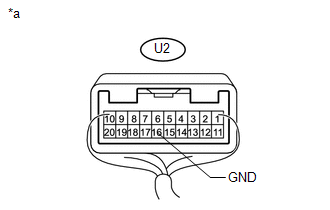
*a |
Component with harness connected (Map Light Assembly) |
| NG | |
REPAIR OR REPLACE HARNESS OR CONNECTOR |
|
|
4. |
INSPECT MAP LIGHT ASSEMBLY (RED INDICATOR) |
|
(a) Disconnect the U2 map light assembly connector. |
|
(b) Connect 2 dry-cell batteries (1.5 V each) in series.
(c) Connect a positive (+) lead of the battery to terminal U2-19 (IND1) and a negative (-) lead to terminal U2-16 (GND) of the map light assembly connector.
(d) Check if the manual (SOS) switch red indicator comes on.
OK:
Red indicator comes on.
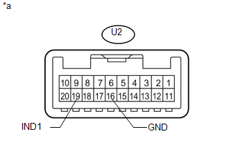
Text in Illustration|
*a |
Component without harness connected (Map Light Assembly) |
| NG | |
REPLACE MAP LIGHT ASSEMBLY |
|
|
5. |
INSPECT MAP LIGHT ASSEMBLY (MANUAL [SOS] SWITCH RED INDICATOR CONDITION) |
(a) Confirm the red indicator status after the ignition switch is turned to ON
(See page ).
Result
|
Result |
Proceed to |
|---|---|
|
Red indicator remains off |
A |
|
Red indicator remains on |
B |
| B | |
GO TO STEP 9 |
|
|
6. |
CHECK MAP LIGHT ASSEMBLY (RED INDICATOR INPUT VOLTAGE) |
|
(a) Remove the map light assembly with the connector connected (See page
|
|
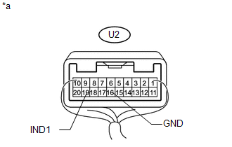
(b) Set a voltmeter to the map light assembly connector terminals, connect a positive (+) lead to terminal U2-19 (IND1) and a negative (-) lead to terminal U2-16 (GND).
(c) Measure the voltage.
OK:
1.0 to 8.5 V in 2 seconds after the ignition switch is turned to ON.
0 V when the ignition switch is turned off.
Text in Illustration|
*a |
Component with harness connected (Map Light Assembly) |
| OK | |
REPLACE MAP LIGHT ASSEMBLY |
|
|
7. |
CHECK DCM (TELEMATICS TRANSCEIVER) (RED INDICATOR OUTPUT VOLTAGE) |
|
(a) Remove the DCM (Telematics Transceiver) with the connectors connected
(See page |
|
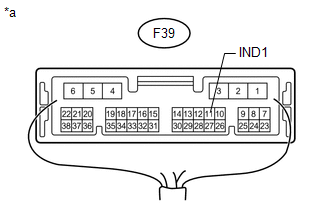
(b) Set a voltmeter to the DCM (Telematics Transceiver) connector terminals, connect a positive (+) lead to terminal F39-11 (IND1) and a negative (-) lead to body ground.
(c) Measure the voltage.
OK:
1.0 to 8.5 V in 2 seconds after the ignition switch is turned to ON.
0 V when the ignition switch is turned off.
Text in Illustration|
*a |
Component with harness connected (DCM [Telematics Transceiver]) |
| OK | |
REPAIR OR REPLACE HARNESS OR CONNECTOR |
|
|
8. |
CHECK HARNESS AND CONNECTOR (DCM - BODY GROUND) |
|
(a) Remove the DCM (Telematics Transceiver) with the connectors connected
(See page |
|
(b) Measure the resistance according to the value(s) in the table below.
Standard Resistance:
|
Tester Connection |
Condition |
Specified Condition |
|---|---|---|
|
F39-11 (IND1) - Body ground |
Always |
10 kΩ or higher |
|
*a |
Component with harness connected (DCM [Telematics Transceiver]) |
| NG | |
REPAIR OR REPLACE HARNESS OR CONNECTOR |
|
|
9. |
REPLACE DCM (TELEMATICS TRANSCEIVER) |
(a) Replace the DCM (Telematics Transceiver) (See page
).
NOTICE:
- The ignition switch must be off.
- Do not replace the DCM (Telematics Transceiver) with one from another vehicle.
| NEXT | |
PERFORM DCM ACTIVATION |
 Airbag Signal Malfunction/Not Input (B15C4)
DESCRIPTION
If the DCM (Telematics Transceiver) detects an error in the communication between
the DCM (Telematics Transceiver) and center airbag sensor assembly as a result of
the DCM (Telematics ...
 Manual (SOS) Switch Green Indicator Malfunction (B1571)
DESCRIPTION
This DTC is stored when the DCM (Telematics Transceiver) detects an open or short
in the manual (SOS) switch green indicator circuit of the manual (SOS) switch. The
manual (SOS) switc ...
Other materials about Toyota 4Runner:
Removal
REMOVAL
PROCEDURE
1. REMOVE JACK BOX HOLE COVER
2. REMOVE REAR QUARTER PANEL MUDGUARD LH
3. REMOVE REAR QUARTER PANEL MUDGUARD RH
HINT:
Use the same procedure as for the LH side.
4. REMOVE REAR BUMPER COVER
(a) Remove the 2 bolts and 2 screws.
...
Dtc Check / Clear
DTC CHECK / CLEAR
1. CHECK FOR DTC
(a) Connect the Techstream to the DLC3.
(b) Turn the ignition switch to ON.
(c) Turn the Techstream on.
(d) Enter the following menus: Body Electrical / Air Conditioner / Trouble Codes.
(e) Check for DTCs.
2. CLEAR DTC ...
0.0065