Toyota 4Runner: Navigation Receiver Assembly Power Source Circuit
DESCRIPTION
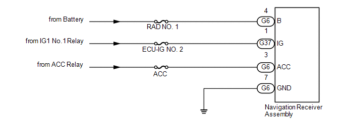
This is the power source circuit to operate the navigation receiver assembly.
WIRING DIAGRAM
CAUTION / NOTICE / HINT
NOTICE:
Inspect the fuses for circuits related to this system before performing the following inspection procedure.
PROCEDURE
|
1. |
CHECK HARNESS AND CONNECTOR (NAVIGATION RECEIVER ASSEMBLY - BATTERY, BODY GROUND) |
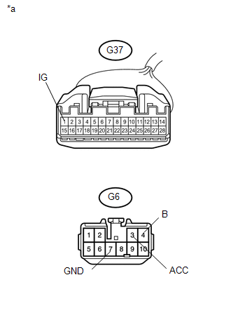
(a) Disconnect the G6 and G37 navigation receiver assembly connectors.
(b) Measure the resistance according to the value(s) in the table below .
Standard Resistance:
|
Tester Connection |
Condition |
Specified Condition |
|---|---|---|
|
G6-7 (GND) - Body ground |
Always |
Below 1 Ω |
|
(c) Measure the voltage according to the value(s) in the table below. Standard Voltage:
|
|
| OK | .gif) |
PROCEED TO NEXT SUSPECTED AREA SHOWN IN PROBLEM SYMPTOMS TABLE |
| NG | |
REPAIR OR REPLACE HARNESS OR CONNECTOR |
 Stereo Component Amplifier Power Source Circuit
DESCRIPTION
This circuit provides power to the stereo component amplifier assembly.
WIRING DIAGRAM
CAUTION / NOTICE / HINT
NOTICE:
Inspect the fuses for circuits related to this system before p ...

Other materials about Toyota 4Runner:
Installation
INSTALLATION
PROCEDURE
1. INSTALL PARK/NEUTRAL POSITION SWITCH ASSEMBLY
(a) Install the switch to the manual valve shaft.
(b) Temporarily install the bolt.
(c) Install a new lock washer and the nut ...
Route cannot be Calculated
PROCEDURE
1.
SET DESTINATION
(a) Set another destination and check if the system can calculate the route correctly.
OK:
Route can be correctly calculated.
OK
NORMAL OPERATION
NG
...
0.0075