Toyota 4Runner: Navigation Voice Circuit
DESCRIPTION
This circuit is used when the voice guidance in the navigation system is on or an incoming cellular phone voice in the "Bluetooth" hands-free system is heard.
Using this circuit, the navigation receiver assembly sends the signals to the stereo component amplifier assembly.
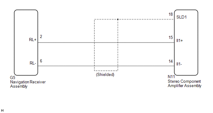
WIRING DIAGRAM
PROCEDURE
|
1. |
CHECK HARNESS AND CONNECTOR (NAVIGATION RECEIVER ASSEMBLY - STEREO COMPONENT AMPLIFIER ASSEMBLY) |
(a) Disconnect the G5 navigation receiver assembly connector.
(b) Disconnect the N11 stereo component amplifier assembly connector.
(c) Measure the resistance according to the value(s) in the table below.
Standard Resistance:
|
Tester connection |
Condition |
Specified condition |
|---|---|---|
|
G5-2 (RL+) - N11-15 (II1+) |
Always |
Below 1 Ω |
|
G5-6 (RL-) - N11-14 (II1-) |
Always |
Below 1 Ω |
|
N11-18 (SLD1) - Body ground |
Always |
10 kΩ or higher |
|
N11-14 (II1-) - Body ground |
Always |
10 kΩ or higher |
|
N11-15 (II1+) - Body ground |
Always |
10 kΩ or higher |
| OK | .gif) |
PROCEED TO NEXT SUSPECTED AREA SHOWN IN PROBLEM SYMPTOMS TABLE |
| NG | |
REPAIR OR REPLACE HARNESS OR CONNECTOR |
 Reverse Signal Circuit
DESCRIPTION
The navigation receiver assembly receives a reverse signal from the park/neutral
position switch assembly.
WIRING DIAGRAM
CAUTION / NOTICE / HINT
NOTICE:
After replacing t ...
 Microphone Circuit between Microphone and Navigation Receiver Assembly
DESCRIPTION
The navigation receiver assembly and map light assembly (telephone microphone
assembly) are connected to each other using the microphone connection detection
signal lines. ...
Other materials about Toyota 4Runner:
Installing child restraints using a seat belt (child restraint lock function
belt)
Rear facing -- Infant seat/convertible seat
Place the child restraint system on the rear seat facing the rear of the
vehicle.
Run the seat belt through the child restraint system and insert the plate
into the buckle. Make sure that the belt is not tw ...
On-vehicle Inspection
ON-VEHICLE INSPECTION
PROCEDURE
1. CHECK INSTRUMENT PANEL PASSENGER AIRBAG ASSEMBLY (VEHICLE NOT INVOLVED IN
COLLISION)
(a) Perform a diagnostic system check (See page
).
(b) With the instrument panel passenger airbag installed on the vehicle, perform ...
0.0272