Toyota 4Runner: On-vehicle Inspection
ON-VEHICLE INSPECTION
PROCEDURE
1. CHECK TURN SIGNAL FLASHER ASSEMBLY
|
(a) Measure the resistance according to the value(s) in the table below. Standard Resistance:
|
|
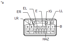
(b) Measure the voltage according to the value(s) in the table below.
Standard Voltage:
|
Tester Connection |
Condition |
Specified Condition |
|---|---|---|
|
8 (LR) - 4 (E) |
Hazard warning switch off |
Below 1 V |
|
Hazard warning switch on |
Alternating between 11 to 14 V and below 1 V (60 to 120 times per minute) |
|
|
2 (LL) - 4 (E) |
Hazard warning switch off |
Below 1 V |
|
Hazard warning switch on |
Alternating between 11 to 14 V and below 1 V (60 to 120 times per minute) |
|
|
1 (B) - 4 (E) |
Always |
11 to 14 V |
|
3 (IG) - 4 (E) |
Ignition switch ON |
11 to 14 V |
|
6 (EL) - 4 (E) |
Ignition switch ON Headlight dimmer switch (turn left) off |
9 V or higher |
|
Ignition switch ON Headlight dimmer switch (turn left) on |
Below 1 V |
|
|
7 (ER) - 4 (E) |
Ignition switch ON Headlight dimmer switch (turn right) off |
9 V or higher |
|
Ignition switch ON Headlight dimmer switch (turn right) on |
Below 1 V |
|
|
12 (HAZ) - 4 (E) |
Hazard warning switch off |
9 V or higher |
|
Hazard warning switch on |
Below 1 V |
If the result is not as specified, there may be a malfunction in the turn signal flasher assembly.
Text in Illustration|
*a |
Component with harness connected (Stop Light Switch Assembly) |
 Components
COMPONENTS
ILLUSTRATION
...
 Removal
REMOVAL
PROCEDURE
1. REMOVE DOOR SCUFF PLATE ASSEMBLY LH
2. REMOVE COWL SIDE TRIM BOARD LH
3. REMOVE NO. 2 SWITCH HOLE BASE
4. REMOVE NO. 1 INSTRUMENT CLUSTER FINISH PANEL GARNISH
5. ...
Other materials about Toyota 4Runner:
ECU Circuit (61)
DESCRIPTION
When the internal circuit of the side auto step controller ECU assembly malfunctions,
the side auto step controller ECU assembly halts the operation of the system.
DTC No.
DTC Detection Condition
Trouble Area
...
Inspection
INSPECTION
PROCEDURE
1. INSPECT STEERING PAD SWITCH ASSEMBLY
(a) Inspect the steering pad switch assembly.
(1) Disconnect the switch connector.
Text in Illustration
*1
Up Switch
*2
Down Switch
...
0.0065