Toyota 4Runner: On-vehicle Inspection
ON-VEHICLE INSPECTION
PROCEDURE
1. REMOVE FRONT WHEEL
2. DISCONNECT FRONT DISC BRAKE CYLINDER ASSEMBLY LH
.gif)
3. REMOVE FRONT DISC
4. REMOVE FRONT AXLE HUB GREASE CAP
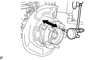
5. INSPECT FRONT AXLE HUB BEARING LOOSENESS
|
(a) Using a dial indicator, measure the looseness near the center of the axle hub. Maximum looseness: 0.05 mm (0.00197 in.) NOTICE: Make sure that the dial indicator is set at a right angle to the measurement surface. If the looseness is more than the maximum, replace the axle hub. |
|
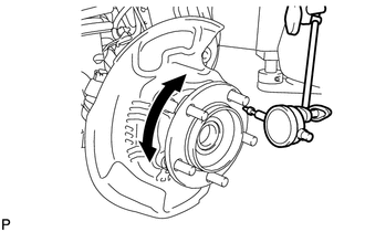
6. INSPECT FRONT AXLE HUB RUNOUT
|
(a) Using a dial indicator, measure the runout on the surface of the axle hub outside the hub bolts. Maximum runout: 0.08 mm (0.00315 in.) NOTICE: Make sure that the dial indicator is set at a right angle to the measurement surface. If the runout is more than the maximum, replace the axle hub. |
|
7. INSTALL FRONT AXLE HUB GREASE CAP
8. INSTALL FRONT DISC
9. INSTALL DISC BRAKE CYLINDER ASSEMBLY LH
10. INSTALL FRONT WHEEL
Torque:
for aluminum wheel :
103 N·m {1050 kgf·cm, 76 ft·lbf}
for steel wheel :
112 N·m {1142 kgf·cm, 83 ft·lbf}
 Components
COMPONENTS
ILLUSTRATION
...
 Removal
REMOVAL
CAUTION / NOTICE / HINT
HINT:
Use the same procedure for the RH and LH sides.
The procedure listed below is for the LH side.
PROCEDURE
1. REMOVE FRONT WHEEL
2. REMOVE D ...
Other materials about Toyota 4Runner:
Data Signal Circuit between Radio Receiver and Extension Module
DESCRIPTION
The stereo component tuner assembly sends the sound data signal or image data
signal from a device to the radio and display receiver assembly via this circuit.
WIRING DIAGRAM
PROCEDURE
1.
CHECK HARNESS AND CONNECTOR ( ...
Transmitter Battery(w/o Smart Key System)
Replacement
REPLACEMENT
CAUTION / NOTICE / HINT
NOTICE:
Take extra care when handling these precision electronic components.
PROCEDURE
1. REMOVE TRANSMITTER HOUSING COVER
(a) Twist a screwdriver in the direction of the arrow in the illustra ...
0.0091