Toyota 4Runner: Open in Pump Motor Circuit (C1251)
DESCRIPTION
The motor relay (semiconductor relay) is built into the master cylinder solenoid and drives the pump motor based on a signal from the skid control ECU.
|
DTC Code |
DTC Detection Condition |
Trouble Area |
|---|---|---|
|
C1251 |
There is an open in the motor system circuit (motor input circuit). |
|
CAUTION / NOTICE / HINT
NOTICE:
When replacing the master cylinder solenoid, perform calibration (See page
.gif) ).
).
HINT:
Remove the hydraulic brake booster assembly before the inspection (See page
).
PROCEDURE
|
1. |
CHECK CONNECTION OF PUMP MOTOR WIRE HARNESS |
(a) Remove the hydraulic brake booster assembly (See page
).
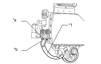
(b) Check the tightening torque of the 2 screws which secure the wire harness
connecting the master cylinder solenoid and brake booster with accumulator pump
assembly (See page ).
OK:
The harness is tightened to the specified torque.
Torque:
2.9 N·m {30 kgf·cm, 26 in·lbf}
| NG | .gif) |
RETIGHTEN SCREWS |
|
.gif)
|
2. |
CHECK RESISTANCE OF PUMP MOTOR WIRE HARNESS |
(a) Using a screwdriver, remove the 2 screws and pull out the wire harness from the master cylinder solenoid.
|
(b) Measure the resistance according to the value(s) in the table below. Standard Resistance:
|
|
| NG | |
REPLACE BRAKE BOOSTER WITH ACCUMULATOR PUMP ASSEMBLY |
|
|
3. |
RECONFIRM DTC |
(a) Reassemble the hydraulic brake booster assembly (See page
).
(b) Install the hydraulic brake booster assembly (See page
).
(c) Clear the DTCs (See page ).
(d) Turn the ignition switch off.
(e) Check if the same DTC is output (See page
).
|
Result |
Proceed to |
|---|---|
|
DTC is output |
A |
|
DTC is not output |
B |
| A | |
REPLACE MASTER CYLINDER SOLENOID |
| B | |
USE SIMULATION METHOD TO CHECK |
 Open Circuit in IG1/IG2 Power Source Circuit (C1242)
DESCRIPTION
If there is a problem with the master cylinder solenoid (skid control ECU) power
supply circuit, the skid control ECU stores DTCs and prohibits operation under the
fail-safe function. ...
 Brake Booster Pump Motor on Time Abnormally Long (C1252)
DESCRIPTION
The motor relay (semiconductor relay) is built into the master cylinder solenoid
and drives the pump motor based on a signal from the skid control ECU.
DTC Code
D ...
Other materials about Toyota 4Runner:
Diagnosis System
DIAGNOSIS SYSTEM
1. CHECK DLC3
(a) Check the DLC3 (See page ).
2. FUNCTION OF POWER STEERING WARNING LIGHT
(a) When a malfunction is detected in the power steering system, the power steering
warning light in the combination meter comes on to inform the ...
Sensor (Motor) Failure (B2341,B2344)
DESCRIPTION
When the sliding roof drive gear sub-assembly detects a motor malfunction
and the sliding roof operation is stopped, DTC B2341 is stored.
When the sliding roof drive gear sub-assembly detects a gear position
malfunctio ...
0.0268