Toyota 4Runner: Operating Light Control Rheostat does not Change Light Brightness
DESCRIPTION
When the light control rheostat dial is turned upward, the combination meter and vehicle interior illumination will become brighter. When the light control rheostat dial is turned downward, the combination meter and vehicle illumination will dim.
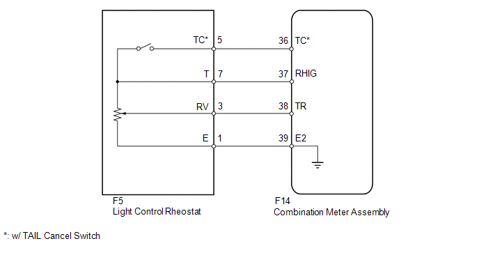
WIRING DIAGRAM
PROCEDURE
|
1. |
READ VALUE USING TECHSTREAM (LIGHT CONTROL RHEOSTAT) |
(a) Operate the Techstream according to the display and select the Data List
(See page .gif) ).
).
Combination Meter
|
Tester Display |
Measurement Item/Range |
Normal Condition |
Diagnostic Note |
|---|---|---|---|
|
Tail Cancel SW* |
TAIL cancel switch condition/ON or OFF |
ON: TAIL cancel switch on OFF: TAIL cancel switch off |
- |
|
Rheostat value |
Light control rheostat switch input/Min.: 0, Max.: 100 |
Light control rheostat switch fully turned downward (0) → fully turned upward (100) |
Unit: % |
- *: w/ TAIL Cancel Switch
OK:
Light brightness can be changed within specified range by manual operation.
| OK | .gif) |
REPLACE COMBINATION METER ASSEMBLY |
|
.gif)
|
2. |
INSPECT LIGHT CONTROL RHEOSTAT |
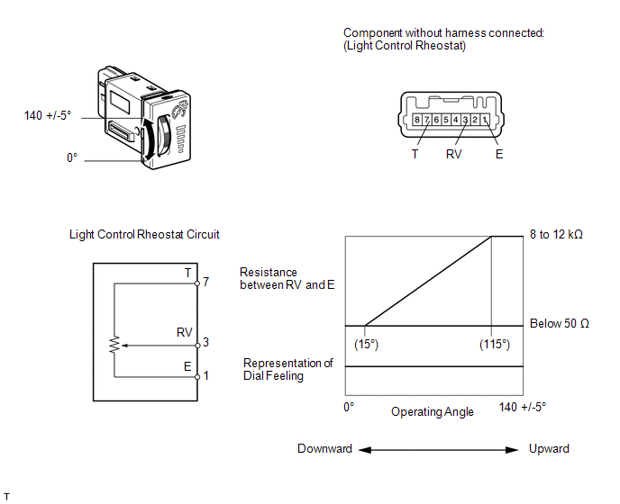
w/o TAIL Cancel Switch:
(a) Inspect the light control rheostat.
(1) Remove the light control rheostat (See page
).
(2) Measure the resistance according to the table below.
Standard Resistance:
|
Tester Connection |
Switch Condition |
Specified Condition |
|---|---|---|
|
7 (T) - 1 (E) |
Always |
8 to 12 kΩ |
|
3 (RV) - 1 (E) |
Light control rheostat fully turned upward → fully turned downward |
8 to 12 kΩ → Below 50 Ω |
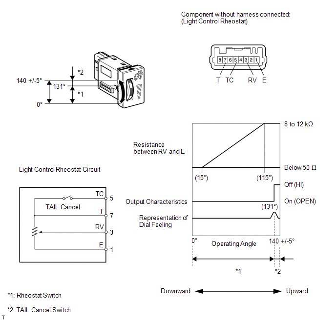
w/ TAIL Cancel Switch:
(b) Inspect the light control rheostat.
(1) Remove the light control rheostat (See page
).
(2) Measure the resistance according to the table below.
Standard Resistance:
|
Tester Connection |
Switch Condition |
Specified Condition |
|---|---|---|
|
7 (T) - 5 (TC) |
TAIL cancel switch off → on |
1 MΩ or higher → Below 1 Ω |
|
7 (T) - 1 (E) |
Always |
8 to 12 kΩ |
|
3 (RV) - 1 (E) |
Light control rheostat fully turned upward → fully turned downward |
8 to 12 kΩ → Below 50 Ω |
| NG | |
REPLACE LIGHT CONTROL RHEOSTAT |
|
|
3. |
CHECK HARNESS AND CONNECTOR (COMBINATION METER - LIGHT CONTROL RHEOSTAT) |
(a) Disconnect the F14 meter connector.
(b) Disconnect the F5 rheostat connector.
(c) Measure the resistance according to the value(s) in the table below.
Standard Resistance:
|
Tester Connection |
Condition |
Specified Condition |
|---|---|---|
|
F14-36 (TC) - F5-5 (TC)* |
Always |
Below 1 Ω |
|
F14-37 (RHIG) - F5-7 (T) |
||
|
F14-38 (TR) - F5-3 (RV) |
||
|
F14-39 (E2) - F5-1 (E) |
- *: w/ TAIL Cancel Switch
| NG | |
REPAIR OR REPLACE HARNESS OR CONNECTOR |
|
|
4. |
REPLACE COMBINATION METER ASSEMBLY |
(a) Replace the combination meter assembly with a new or normally functioning one. Perform an operation inspection.
OK:
Combination meter assembly operates normally.
| OK | |
END |
| NG | |
GO TO LIGHTING SYSTEM |
 Engine Coolant Temperature Receiver Gauge Malfunction
DESCRIPTION
In this circuit, the meter CPU receives engine coolant temperature signals from
the ECM using the CAN communication system. The meter CPU displays the engine coolant
temperature, whic ...
 Meter Illumination does not Dim at Night
DESCRIPTION
If the dimmer switch is turned to TAIL, HEAD or AUTO, the main body ECU sends
a TAIL relay signal, panel light illumination signal, panel relay signal and TAIL
cancel OFF signal to th ...
Other materials about Toyota 4Runner:
Windshield wiper de-icer
This feature is used to prevent ice from building up on the windshield and
wiper blades.
Turns the windshield wiper deicer on/off
The windshield wiper de-icer will automatically turn off after approximately
15 minutes.
The windshield wiper de-icer can ...
On-vehicle Inspection
ON-VEHICLE INSPECTION
PROCEDURE
1. CHECK STEERING PAD (VEHICLE NOT INVOLVED IN COLLISION)
(a) Perform a diagnostic system check (See page
).
(b) With the steering pad installed on the vehicle, perform a visual check. If
there are any defects as mention ...
0.0072