Toyota 4Runner: Parking Brake Switch Circuit
DESCRIPTION
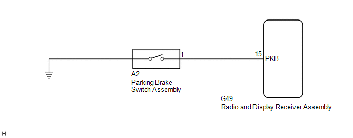
This circuit is from the parking brake switch assembly to the radio and display receiver assembly.
WIRING DIAGRAM
PROCEDURE
|
1. |
CHECK BRAKE WARNING LIGHT |
(a) Check that the brake warning light comes on when the parking brake is applied and goes off when it is released.
OK:
The brake warning light operates as specified above.
| NG | .gif) |
GO TO BRAKE CONTROL / DYNAMIC CONTROL SYSTEMS |
|
.gif)
|
2. |
CHECK HARNESS AND CONNECTOR (PARKING BRAKE SWITCH ASSEMBLY - RADIO AND DISPLAY RECEIVER ASSEMBLY) |
(a) Disconnect the G49 radio and display receiver assembly connector.
(b) Disconnect the A2 parking brake switch assembly connector.
(c) Measure the resistance according to the value(s) in the table below.
Standard Resistance:
|
Tester Connection |
Condition |
Specified Condition |
|---|---|---|
|
G49-15 (PKB) - A2-1 |
Always |
Below 1 Ω |
|
G49-15 (PKB) - Body ground |
Always |
10 kΩ or higher |
| OK | |
PROCEED TO NEXT SUSPECTED AREA SHOWN IN PROBLEM SYMPTOMS TABLE |
| NG | |
REPAIR OR REPLACE HARNESS OR CONNECTOR |
 Illumination Circuit
DESCRIPTION
Power is supplied to the radio and display receiver assembly and steering pad
switch illumination when the light control switch is in the tail or head position.
WIRING DIAGRAM
CAUTI ...
 Speaker Circuit
DESCRIPTION
If there is a short in a speaker circuit, the radio and display receiver assembly
detects it and stops output to the speakers.
Thus sound cannot be heard from the speakers even if ther ...
Other materials about Toyota 4Runner:
Disassembly
DISASSEMBLY
PROCEDURE
1. REMOVE BRAKE FLUID INFORMATION LABEL
2. REMOVE BRAKE MASTER CYLINDER RESERVOIR FILLER CAP ASSEMBLY
(a) Remove the brake master cylinder reservoir filler cap assembly from the brake
master cylinder reservoir assembly.
3. REMOVE B ...
Inspection
INSPECTION
CAUTION / NOTICE / HINT
NOTICE:
Make sure that fingers or articles of clothing do not get caught in moving parts
when performing this test.
PROCEDURE
1. INSPECT WINDSHIELD WIPER MOTOR ASSEMBLY
(a) Check the LO operation.
(1) Co ...
0.0275