Toyota 4Runner: Power Steering Warning Light Circuit
DESCRIPTION
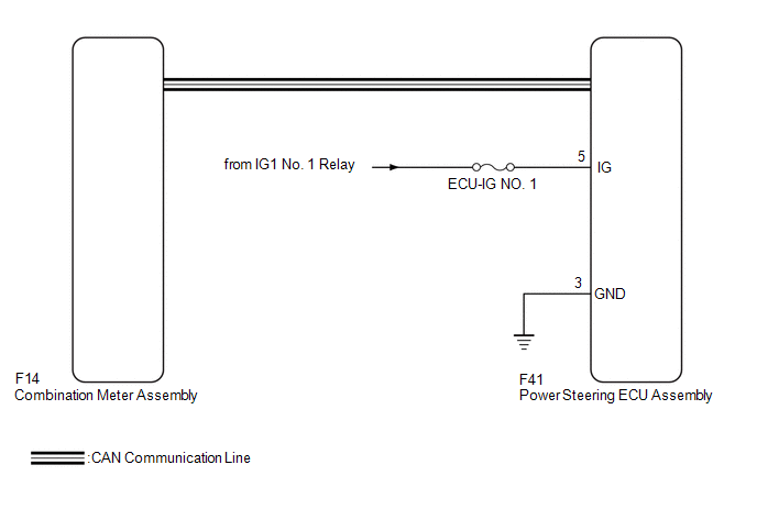
The power steering ECU assembly is connected to the combination meter assembly via CAN communication. If the power steering ECU assembly detects a malfunction, the power steering warning light comes on. At this time, the vehicle enters fail-safe mode.
WIRING DIAGRAM
CAUTION / NOTICE / HINT
NOTICE:
Inspect the fuses for circuits related to this system before performing the following inspection procedure.
PROCEDURE
|
1. |
INSPECT CAN COMMUNICATION SYSTEM |
(a) Check for DTCs of the CAN communication system (See page
.gif) ).
).
Result
|
Result |
Proceed to |
|---|---|
|
DTC is not output |
A |
|
DTC is output |
B |
| B | .gif) |
GO TO CAN COMMUNICATION SYSTEM (HOW TO PROCEED WITH TROUBLESHOOTING) |
|
.gif)
|
2. |
CHECK HARNESS AND CONNECTOR (POWER STEERING ECU ASSEMBLY - BATTERY AND BODY GROUND) |
|
(a) Disconnect the F41 power steering ECU assembly connector. |
|
(b) Measure the voltage according to the value(s) in the table below.
Standard Voltage:
|
Tester Connection |
Switch Condition |
Specified Condition |
|---|---|---|
|
F41-5 (IG) - Body ground |
Ignition switch ON |
11 to 14 V |
(c) Measure the resistance according to the value(s) in the table below.
Standard Resistance:
|
Tester Connection |
Condition |
Specified Condition |
|---|---|---|
|
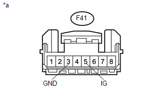
F41-3 (GND) - Body ground |
Always |
Below 1 Ω |
|
*a |
Front view of wire harness connector (to Power Steering ECU Assembly) |
| NG | |
REPAIR OR REPLACE HARNESS OR CONNECTOR |
|
|
3. |
PERFORM ACTIVE TEST USING TECHSTREAM (METER/GAUGE SYSTEM) |
(a) Connect the Techstream to the DLC3.
(b) Turn the ignition switch to ON and turn the Techstream on.
(c) Perform the Active Test of the combination meter using the Techstream (See
page ).
Combination Meter
|
Tester Display |
Test Part |
Control Range |
Diagnostic Note |
|---|---|---|---|
|
PPS Indicator |
Power steering warning light |
ON or OFF |
Perform the test with the vehicle stopped and the engine idling. |
(d) Check that the power steering warning light operates in accordance with the Active Test.
HINT:
Reconnect the connectors and restore the vehicle to its previous condition before checking the combination meter.
OK:
The power steering warning light turns on and off in accordance with the Techstream operation.
| OK | |
REPLACE POWER STEERING ECU ASSEMBLY |
| NG | |
INSPECT METER/GAUGE SYSTEM (HOW TO WITH PROCEED TROUBLESHOOTING) |
 High Engine Revolution Signal (C1544)
DESCRIPTION
The power steering ECU assembly receives engine speed signals from the ECM via
CAN communication. The power steering ECU assembly provides appropriate assisting
force in accordance wi ...
 IG Power Source Circuit
DESCRIPTION
When the ignition switch is turned to ON, the IG power source circuit supplies
positive (+) voltage to the power steering ECU assembly.
WIRING DIAGRAM
CAUTION / NOTICE / HINT
NOTIC ...
Other materials about Toyota 4Runner:
IG Power Source Circuit
DESCRIPTION
The main power source is supplied to the air conditioning amplifier assembly
when the ignition switch is turned to ON. The power source is used for operating
the air conditioning amplifier assembly, servo motors, etc.
WIRING DIAGRAM
CAUTIO ...
SRS airbag system components
1. Side airbags
2. “AIR BAG ON” and “AIR BAG OFF” indicator lights
3. Curtain shield airbags
4. Front passenger airbag
5. Knee airbags
6. Side and curtain shield airbag sensors
7. Seat belt pretensioners and force limiters
8. Front airba ...
0.0276