Toyota 4Runner: Precaution
PRECAUTION
1. IGNITION SWITCH EXPRESSION
HINT:
The type of ignition switch used on this model differs according to the specifications of the vehicle. The expressions listed in the table below are used in this section.
|
Expression |
Ignition Switch (position) |
Engine Switch (condition) |
|---|---|---|
|
Ignition Switch off |
Off |
Off |
|
Ignition Switch ON |
ON |
On (IG) |
|
Ignition Switch ACC |
ACC |
On (ACC) |
|
Engine Start |
START |
Start |
2. STEERING SYSTEM HANDLING PRECAUTIONS
(a) Care must be taken when replacing parts. Incorrect replacement could affect the performance of the steering system and result in hazards when driving.
3. SRS AIRBAG SYSTEM HANDLING PRECAUTIONS
(a) This vehicle is equipped with an SRS (Supplemental Restraint System), which
includes components such as the driver airbag and front passenger airbag. Failure
to carry out service operations in the correct sequence could cause unexpected SRS
deployment during servicing and may lead to a serious accident. Before servicing
(including installation/removal, inspection and replacement of parts), be sure to
read the precautionary notice for the Supplemental Restraint System (See page
.gif) ).
).
4. BUS LINE REPAIR
(a) After repairing the bus line with solder, wrap the repaired part with vinyl
tape (See page ).

NOTICE:
- The CANL bus line and CANH bus line must be installed together.
- When installing the CAN bus lines, be sure to twist them.
- CAN bus lines are likely to be influenced by noise if the bus lines are not twisted together.
- The difference in length between the CANL bus line and CANH bus line should be less than 100 mm (3.94 in.).
- Leave approximately 80 mm (3.15 in.) loose in the twisted wires around the connectors.
(b) Do not use by-pass wiring between the connectors.

NOTICE:
The protective effect of the twisted wire harness is lost if bypass wiring is used.
Text in Illustration|
*1 |
By-pass Wire |
5. CONNECTOR HANDLING
(a) When inserting probes into a connector, insert them from the rear of the connector.
 Text in Illustration
|
*1 |
Tester Probe |
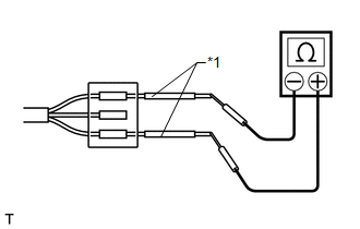
(b) Use a repair wire to check the connector if it is impossible to check resistance from the rear of the connector.
Text in Illustration|
*1 |
Repair Wire |

 Parts Location
PARTS LOCATION
ILLUSTRATION
ILLUSTRATION
ILLUSTRATION
ILLUSTRATION
ILLUSTRATION
...
Other materials about Toyota 4Runner:
Adjustment
ADJUSTMENT
CAUTION / NOTICE / HINT
NOTICE:
If the wheel alignment has been adjusted, and if suspension or underbody components
have been removed/installed or replaced, be sure to perform the following initialization
procedure in order for the system to ...
Center Airbag Sensor Assembly Malfunction (B1000/31)
DESCRIPTION
The center airbag sensor assembly consists of a deceleration sensor, safing sensor,
drive circuit, diagnosis circuit, ignition control, etc.
If the center airbag sensor assembly receives signals from the deceleration sensor,
it determines whe ...
0.0261