Toyota 4Runner: Rear Lateral Control Rod
Components
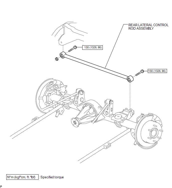
COMPONENTS
ILLUSTRATION
Removal
REMOVAL
PROCEDURE
1. REMOVE REAR LATERAL CONTROL ROD ASSEMBLY
|
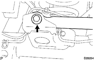
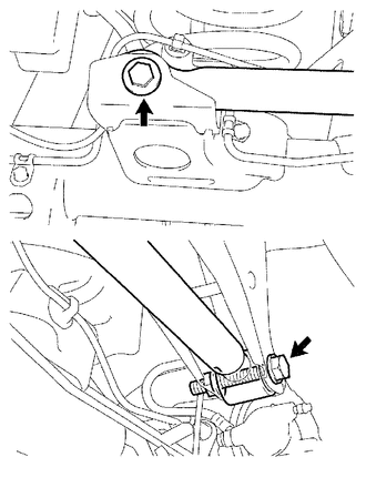
(a) Remove the bolt. |
|
|
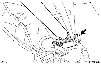
(b) Remove the bolt, nut and lateral control rod assembly. HINT: Turn the bolt while holding the nut. |
|
Installation
INSTALLATION
PROCEDURE
1. TEMPORARILY INSTALL REAR LATERAL CONTROL ROD ASSEMBLY
(a) Temporarily install the lateral control rod assembly with the bolt and nut.
(b) Temporarily tighten the bolt.
2. STABILIZE SUSPENSION
.gif)
3. TIGHTEN REAR LATERAL CONTROL ROD ASSEMBLY
|
(a) Tighten the 2 bolts. Torque: 130 N·m {1326 kgf·cm, 96 ft·lbf} HINT: Turn the bolt while holding the nut. |
|
 Rear Coil Spring
Components
COMPONENTS
ILLUSTRATION
Removal
REMOVAL
CAUTION / NOTICE / HINT
HINT:
Use the same procedure for the RH and LH sides.
The procedure listed below is for the LH side. ...
 Rear Lower Arm
Components
COMPONENTS
ILLUSTRATION
Removal
REMOVAL
CAUTION / NOTICE / HINT
HINT:
Use the same procedure for the RH and LH sides.
The procedure listed below is for the LH side. ...
Other materials about Toyota 4Runner:
Rear Power Window RH Auto Up / Down Function does not Operate with Rear Power
Window Switch RH
DESCRIPTION
If the auto up/down function does not operate, the cause may be one or more of
the following:
The ECU in the power window regulator motor determines that the power
window regulator motor has not been initialized.
The rear power w ...
Registered Device cannot be Deleted
PROCEDURE
1.
DELETE OPERATION
(a) Check if a registered portable player can be deleted normally.
OK:
Registered portable player can be deleted normally.
OK
USE SIMULATION METHOD TO CHECK
...
0.0253