Toyota 4Runner: Rear Shock Absorber(w/o Reas)
Components
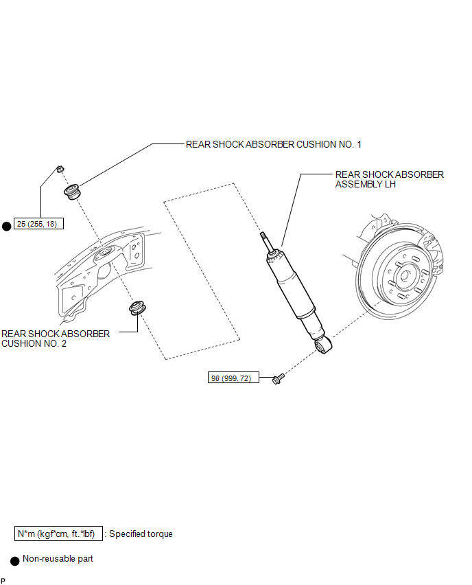
COMPONENTS
ILLUSTRATION
Removal
REMOVAL
CAUTION / NOTICE / HINT
HINT:
- Use the same procedure for the RH and LH sides.
- The procedure listed below is for the LH side.
PROCEDURE
1. REMOVE REAR WHEEL
2. REMOVE REAR SHOCK ABSORBER ASSEMBLY LH
(a) Support the rear axle housing.
|
(b) Remove the bolt and disconnect the rear shock absorber assembly LH from the rear axle housing. |
|
.png)
|
(c) Remove the nut, cushion No. 1 and rear shock absorber assembly LH. |
|
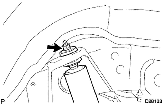
(d) Remove the cushion No. 2 from the shock absorber assembly rear LH.
Inspection
INSPECTION
PROCEDURE
1. INSPECT REAR SHOCK ABSORBER ASSEMBLY LH
(a) Compress and extend the shock absorber rod and check that there is no abnormal resistance or unusual sound during operation.
If there is any abnormality, replace the shock absorber with a new one.
NOTICE:
When disposing of the shock absorber, refer to Disposal (See page
.gif) ).
).
Installation
INSTALLATION
CAUTION / NOTICE / HINT
HINT:
- Use the same procedure for the RH and LH sides.
- The procedure listed below is for the LH side.
- A bolt without a torque specification is shown in the standard bolt
chart (See page
.gif) ).
).
PROCEDURE
1. TEMPORARILY INSTALL REAR SHOCK ABSORBER ASSEMBLY LH
(a) Install the cushion No. 2 to the rear shock absorber assembly LH.
(b) Temporarily install the cushion No. 1 and rear shock absorber assembly LH with a new nut.
(c) Temporarily install the rear shock absorber assembly LH with the bolt.
(d) Tighten the nut.
Torque:
25 N·m {255 kgf·cm, 18 ft·lbf}
2. INSTALL REAR WHEEL
Torque:
for aluminum wheel :
103 N·m {1050 kgf·cm, 76 ft·lbf}
for steel wheel :
112 N·m {1142 kgf·cm, 83 ft·lbf}
3. STABILIZE SUSPENSION
(a) Lower the vehicle.
(b) Bounce the vehicle up and down several times to stabilize the suspension.
4. TIGHTEN REAR SHOCK ABSORBER ASSEMBLY LH
(a) Tighten the bolt.
Torque:
98 N·m {999 kgf·cm, 72 ft·lbf}
Disposal
DISPOSAL
PROCEDURE
1. DISPOSE OF REAR SHOCK ABSORBER ASSEMBLY LH
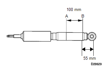
(a) Fully extend the rear shock absorber rod.
|
(b) Using a drill, make a hole in the cylinder between A and B in the illustration to discharge the gas inside. CAUTION: Be careful when drilling because shards of metal may fly about. Always use the proper safety equipment. NOTICE: The gas is colorless, odorless and harmless. |
|
 Rear Shock Absorber(w/ Reas)
Components
COMPONENTS
ILLUSTRATION
Removal
REMOVAL
CAUTION / NOTICE / HINT
NOTICE:
Be sure to read the precaution before performing this procedure (See page
).
HINT:
Use the s ...

Other materials about Toyota 4Runner:
Image from Camera for Rear View Monitor is Abnormal
DESCRIPTION
The display signal from the rear television camera assembly transmits to the
radio and display receiver assembly.
WIRING DIAGRAM
PROCEDURE
1.
CHECK HARNESS AND CONNECTOR (RADIO AND DISPLAY RECEIVER ASSEMBLY - REAR
...
Capacity and distribution
Cargo capacity depends on the total weight of the occupants.
(Cargo capacity) = (Total load capacity) — (Total weight of occupants) Steps
for Determining Correct Load Limit-- (1)Locate the statement “The combined
weight of occupants and cargo should n ...
0.0073