Toyota 4Runner: Reassembly
REASSEMBLY
PROCEDURE
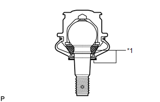
1. INSTALL LOWER BALL JOINT DUST COVER LH
(a) Pack the lower arm ball joint with MP grease.
Grease capacity:
8.0 g (0.282 oz.)
|
(b) Apply MP grease to the locations shown in the illustration. Text in Illustration
NOTICE: Do not apply MP grease to the tapered or threaded parts of the ball joint. |
|
(c) Install the dust cover to the lower arm.
|
(d) Using a snap ring expander, install the dust cover set ring. NOTICE: Make sure the set ring is securely installed in the groove. |
|
.png)
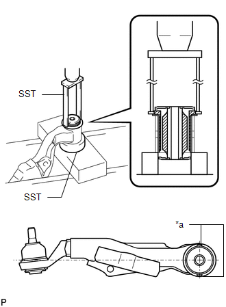
2. INSTALL FRONT NO. 2 LOWER ARM BUSH LH
|
(a) Using SST and a press, press in a new bush. SST: 09387-00020 SST: 09710-30041 09710-03221 Text in Illustration
NOTICE: Press in the bush while making sure the bush positioning protrusions are perpendicular to the lower arm as shown in the illustration. |
|
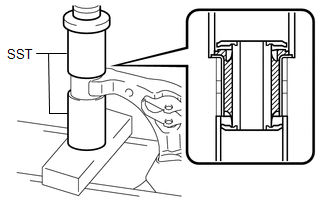
3. INSTALL FRONT NO. 1 LOWER ARM BUSH LH
|
(a) Using SST and a press, press in a new bush. SST: 09612-30012 SST: 09710-30012 09710-04081 |
|
 Installation
INSTALLATION
CAUTION / NOTICE / HINT
HINT:
Use the same procedure for the RH and LH sides.
The procedure listed below is for the LH side.
A bolt without a torque specification is sh ...

Other materials about Toyota 4Runner:
Acceleration Sensor Circuit Malfunction (C1887/87)
DESCRIPTION
The stabilizer control ECU receives forward, backward and lateral acceleration
information from the yaw rate and acceleration sensor via CAN communication.
DTC Code
DTC Detection Condition
Trouble Area
...
Fuel Sender Open Detected (B1500)
DESCRIPTION
This DTC is stored when the combination meter detects a fuel sender gauge malfunction.
DTC Code
DTC Detection Condition
Trouble Area
B1500
IG voltage is 9.5 V or higher and the followin ...
0.0066