Toyota 4Runner: Reassembly
REASSEMBLY
PROCEDURE
1. INSTALL NO. 2 ANTENNA CORD SUB-ASSEMBLY
(a) w/o Sliding Roof:
Install the No. 2 antenna cord sub-assembly (See page
.gif) ).
).
(b) w/ Sliding Roof:
Install the No. 2 antenna cord sub-assembly (See page
).
2. INSTALL NO. 1 ROOF WIRE
(a) Apply butyl tape to the roof headlining so that the tape is aligned with the wire harness marking as shown in the illustration.
HINT:
Use butyl tape that has a width of 10 mm (0.394 in.).
 Text in Illustration
|
*A |
w/o Sliding Roof |
*B |
w/ Sliding Roof |
|
*1 |
Wire Harness Marking |
*2 |
Butyl Tape |
(b) Align the marking tape on the No. 1 roof wire with the roof tongue of the roof headlining as shown in the part of the illustration labeled A and attach the wire to the hook.
(c) Align the marking tape on the No. 1 roof wire with the V mark on the roof headlining as shown in the part of the illustration labeled B and attach the wire to the roof headlining to install it.
HINT:
- For the area in the illustration labeled E, attach the No. 1 roof wire so that its marked surface contacts the roof headlining.
- Be sure to securely attach the roof wire so that it is not twisted.
(d) Attach each clamp.
(e) Turn the visor connectors approximately 90° clockwise to install them to the roof headlining.
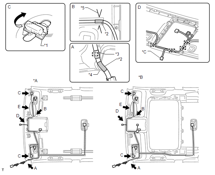 Text in Illustration
|
*A |
w/o Sliding Roof |
*B |
w/ Sliding Roof |
|
*C |
w/ EC Mirror |
- |
- |
|
*1 |
Visor Connector |
*2 |
Marking Tape |
|
*3 |
Hook |
*4 |
Roof Tongue |
|
*5 |
V Mark |
- |
- |
3. INSTALL VANITY LIGHT ASSEMBLY
HINT:
Use the same procedure for the other vanity light.
(a) Attach the 3 claws to install the vanity light.
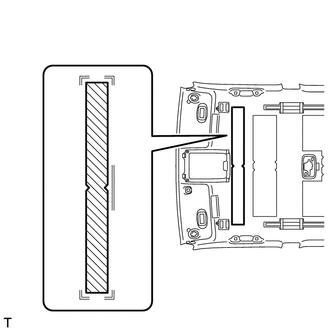
4. INSTALL NO. 4 ROOF SILENCER PAD
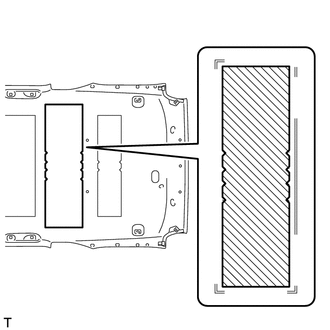
(a) w/o Sliding Roof:
Align the No. 4 roof silencer pad with the markings on the roof headlining and install the No. 4 roof silencer pad to the position shown in the illustration using hot-melt glue or double-sided tape.
|
(b) w/ Sliding Roof: Align the No. 4 roof silencer pad with the markings on the roof headlining and install the No. 4 roof silencer pad to the position shown in the illustration using hot-melt glue or double-sided tape. |
|
5. INSTALL NO. 3 ROOF SILENCER PAD (w/o Sliding Roof)
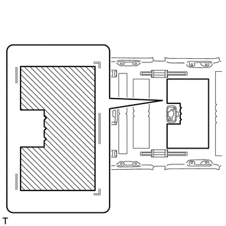
(a) Align the No. 3 roof silencer pad with the markings on the roof headlining and install the No. 3 roof silencer pad to the position shown in the illustration using hot-melt glue or double-sided tape.
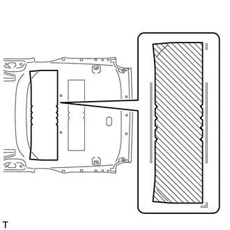
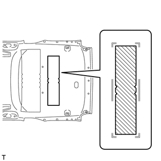
6. INSTALL NO. 2 ROOF SILENCER PAD
(a) w/o Sliding Roof:
Align the 2 No. 2 roof silencer pads with the markings on the roof headlining and install the 2 No. 2 roof silencer pads to the position shown in the illustration using hot-melt glue or double-sided tape.
|
(b) w/ Sliding Roof: Align the No. 2 roof silencer pad with the markings on the roof headlining and install the No. 2 roof silencer pad to the position shown in the illustration using hot-melt glue or double-sided tape. |
|
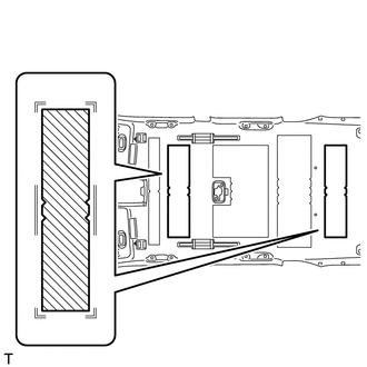
7. INSTALL NO. 1 ROOF SILENCER PAD (w/o Sliding Roof)
(a) Align the No. 1 roof silencer pad with the markings on the roof headlining and install the No. 1 roof silencer pad to the position shown in the illustration using hot-melt glue or double-sided tape.
 Disassembly
DISASSEMBLY
PROCEDURE
1. REMOVE NO. 1 ROOF SILENCER PAD (w/o Sliding Roof)
(a) Remove the No. 1 roof silencer pad.
2. REMOVE NO. 2 ROOF SILENCER PAD
(a) w/o Sliding Roof:
Remove the 2 No. 2 ...
 Installation
INSTALLATION
CAUTION / NOTICE / HINT
HINT:
A bolt without a torque specification is shown in the standard bolt chart (See
page ).
PROCEDURE
1. INSTALL DECK SIDE TRIM CUP HOLDER LH (w/ Rear No. ...
Other materials about Toyota 4Runner:
Short in Sensor with Motor Power Supply Circuit (B2658)
DESCRIPTION
This DTC is stored when a power seat motor operates (a position control sensor
is being supplied with power) and the power supply voltage does not rise to the
specified value.
DTC Code
DTC Detection Condition
...
ECM Communication Circuit Malfunction (C1203)
DESCRIPTION
The circuit is used to send control information from the skid control ECU to
the ECM, and engine control information from the ECM to the skid control ECU via
the CAN communication system.
DTC Code
DTC Detection Condition ...
0.0265