Toyota 4Runner: Reassembly
REASSEMBLY
PROCEDURE
1. INSTALL BRAKE BOOSTER PISTON SIB-ASSEMBLY
|
(a) Apply a light coat of lithium soap base glycol grease to a new piston. |
|
(b) Install the piston.
NOTICE:
When installing, be careful not to damage the seals, etc.
(c) Install the piston.
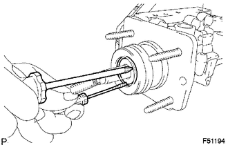
(d) Using 2 screwdrivers, install a new snap C-ring while pressing in the piston.
HINT:
Tape the screwdriver tip before use.
2. INSTALL MASTER CYLINDER BOOT
3. INSTALL MASTER CYLINDER PUSH ROD CLEVIS
(a) Install the brake master cylinder side lock nut and rod operating adapter to the brake master cylinder.
Torque:
26 N·m {260 kgf·cm, 19 ft·lbf}
(b) Install the lock nut and master cylinder push rod clevis to the rod operating adapter.
Torque:
26 N·m {260 kgf·cm, 19 ft·lbf}
4. INSTALL MASTER CYLINDER SOLENOID
(a) Install a new gasket.
NOTICE:
Keep all surfaces of the master cylinder solenoid, master cylinder and gasket, especially contact surfaces, away from water and dust.
(b) Install the master cylinder solenoid with 6 new bolts.
Torque:
32 N·m {326 kgf·cm, 24 ft·lbf}
5. INSTALL BRAKE BOOSTER ACCUMULATOR PIPE
(a) Install the brake booster accumulator pipe and compression spring.
NOTICE:
Make sure that no foreign matter enters the pump.
(b) Install a new O-ring to the brake booster accumulator assembly.
(c) Install the brake booster accumulator assembly.
Torque:
57 N·m {585 kgf·cm, 42 ft·lbf}
6. INSTALL NO. 3 BRAKE ACTUATOR BRACKET
(a) Install the No. 3 brake actuator bracket.
Torque:
7.8 N·m {80 kgf·cm, 69 in·lbf}
7. INSTALL NO. 1 BRAKE BOOSTER PUMP BRACKET
(a) Install the brake booster pump bush to the No. 1 brake booster pump bracket.
(b) Using a 5 mm hexagon wrench, install the No. 1 brake booster pump bracket with the 2 bolts.
Torque:
7.8 N·m {80 kgf·cm, 69 in·lbf}
8. INSTALL BRAKE BOOSTER WITH ACCUMULATOR PUMP ASSEMBLY
(a) Using a 4 mm hexagon wrench, install the 2 pins to the brake master cylinder.
Torque:
7.8 N·m {80 kgf·cm, 69 in·lbf}
(b) Install 2 new brake booster pump collars and 2 brake booster pump bushes to the brake booster with accumulator pump assembly.
(c) Install the brake booster with accumulator pump assembly to the brake master cylinder.
|
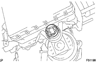
(d) Install a new clip. |
|
|
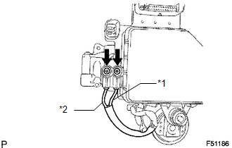
(e) Connect the wire harnesses with the 2 screws. Torque: 2.9 N·m {30 kgf·cm, 26 in·lbf} Text in Illustration
|
|
(f) Install 2 new plugs.
9. INSTALL NO. 1 BRAKE ACTUATOR TUBE
(a) Using a union nut wrench, install the No. 1 brake actuator tube.
Torque:
15 N·m {155 kgf·cm, 11 ft·lbf}
NOTICE:
Use the formula to calculate special torque values for situations where a union
nut wrench is combined with a torque wrench (See page
.gif) ).
).
10. INSTALL NO. 1 BRAKE ACTUATOR HOSE
(a) Using needle nose pliers, install the brake actuator hose with the 2 clips.
11. INSTALL MASTER CYLINDER RESERVOIR GROMMET
|
(a) Apply a light coat of lithium soap base glycol grease to 3 new reservoir grommets. |
|
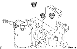
(b) Install the 3 reservoir grommets to the brake master cylinder.
HINT:
Be careful of the size of each grommet.
12. INSTALL BRAKE MASTER CYLINDER RESERVOIR SUB-ASSEMBLY
(a) Install the brake master cylinder reservoir sub-assembly with the screw.
Torque:
1.7 N·m {17 kgf·cm, 15 in·lbf}
(b) Install the master cylinder reservoir filler cap.
(c) Using a pin punch and hammer, install a new pin to the brake master cylinder reservoir sub-assembly.
13. INSTALL NO. 1BRAKE ACTUATOR BRACKET
(a) Install the brake fluid level warning switch connector to the No. 1 brake actuator bracket.
(b) Using a 5 mm hexagon wrench, install the No. 1 brake actuator bracket with the bolt.
Torque:
7.8 N·m {80 kgf·cm, 69 in·lbf}
 Inspection
INSPECTION
PROCEDURE
1. INSPECT BRAKE BOOSTER PUMP ASSEMBLY
(a) Apply battery voltage to the brake booster pump cables, and check
the operation of the pump motor.
OK::
...
 Installation
INSTALLATION
PROCEDURE
1. INSTALL BRAKE BOOSTER GASKET
(a) Install a new brake booster gasket to the hydraulic brake booster.
2. INSTALL HYDRAULIC BRAKE BOOSTER ASSEMBLY
(a) Install the hydraulic ...
Other materials about Toyota 4Runner:
Inspection
INSPECTION
PROCEDURE
1. INSPECT FRONT DRIVE SHAFT ASSEMBLY
NOTICE:
Keep the drive shaft level while handling it.
(a) Check if there is excessive play in the outboard joint.
(b) Check if the inboard joint shaft slides smoothly in the thrust direction.
...
Lost Communication with Combination Meter (B2661,B2662)
DESCRIPTION
This DTC is stored when LIN communication between the drive monitor switch and
combination meter assembly stops 10 seconds or more.
DTC Code
DTC Detection Condition
Trouble Area
B2661
...
0.0256