Toyota 4Runner: Removal
REMOVAL
CAUTION / NOTICE / HINT
NOTICE:
Be sure to read the precaution before performing this procedure (See page
.gif) ).
).
HINT:
- Use the same procedure for the RH and LH sides.
- The procedure listed below is for the LH side.
PROCEDURE
1. REMOVE FRONT WHEEL
2. REMOVE LOWER FRONT BUMPER COVER
3. REMOVE NO. 1 ENGINE UNDER COVER SUB-ASSEMBLY
4. REMOVE FRONT SUSPENSION MEMBER BRACE SUB-ASSEMBLY
5. REMOVE FRONT STABILIZER END BRACKET (w/ KDSS)
6. REMOVE FRONT STABILIZER BAR (w/ KDSS)
7. DISCONNECT FRONT STABILIZER LINK ASSEMBLY LH (w/o KDSS)
|
(a) Remove the nut and disconnect the stabilizer link from the steering knuckle. HINT: If the ball joint turns together with the nut, use a 6 mm hexagon wrench to hold the stud. |
|
8. DISCONNECT FRONT STABILIZER LINK ASSEMBLY RH (w/o KDSS)
HINT:
Use the same procedure described for the LH side.
9. REMOVE FRONT NO. 1 STABILIZER BRACKET LH (w/o KDSS)
10. REMOVE FRONT NO. 1 STABILIZER BRACKET RH (w/o KDSS)
11. REMOVE FRONT STABILIZER BAR (w/o KDSS)
12. REMOVE FRONT SHOCK ABSORBER WITH COIL SPRING (w/ REAS)
NOTICE:
Perform this procedure with the vehicle jacked up so that all the shock absorbers are extended.
|
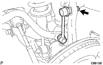
(a) As shown in the illustration, loosen the nut and disconnect the tube. Text in Illustration
NOTICE: Never loosen the absorber hoses or the flare nuts at the joint parts. |
|

|
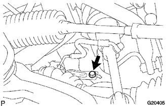
(b) Remove the bolt and bracket. |
|
|
(c) Remove the bolt, nut and washer. |
|
.png)
|
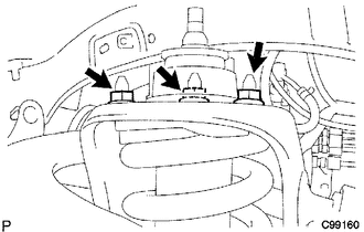
(d) Remove the 3 nuts on the top of the front shock absorber with coil spring. |
|
13. REMOVE FRONT SHOCK ABSORBER WITH COIL SPRING (w/o REAS)
|
(a) Remove the bolt, nut and washer. |
|
|
(b) Remove the 3 nuts on the top of the front shock absorber with coil spring. |
|
(c) Remove the front shock absorber with coil spring.
 Components
COMPONENTS
ILLUSTRATION
ILLUSTRATION
ILLUSTRATION
...
 Disassembly
DISASSEMBLY
PROCEDURE
1. REMOVE FRONT SUPPORT TO FRONT SHOCK ABSORBER NUT
(a) Secure SST in a vise.
SST: 09727-30021
09727-00010
09727-00031
SST: 09727-00060
...
Other materials about Toyota 4Runner:
Terminals Of Ecu
TERMINALS OF ECU
1. CHECK DRIVER SIDE JUNCTION BLOCK ASSEMBLY, MAIN BODY ECU (MULTIPLEX NETWORK
BODY ECU)
(a) Remove the main body ECU (multiplex network body ECU) (See page
).
(b) Measure the voltage and resistance according to the value(s) in the ta ...
Trailer towing
Your vehicle is designed primarily as a passenger-and-load-carrying
vehicle. Towing a trailer can have an adverse impact on handling, performance,
braking, durability, and fuel consumption. For your safety and the safety of
others, you must not overload ...
0.0272