Toyota 4Runner: Removal
REMOVAL
PROCEDURE
1. DISCONNECT CABLE FROM NEGATIVE BATTERY TERMINAL
CAUTION:
Wait at least 90 seconds after disconnecting the cable from the negative (-) battery terminal to disable the SRS system.
NOTICE:
When disconnecting the cable, some systems need to be initialized after the cable
is reconnected (See page .gif) ).
).
2. REMOVE FRONT WHEEL
3. REMOVE REAR WHEEL
4. REMOVE SIDE STEP ASSEMBLY LH
5. REMOVE NO. 1 ENGINE UNDER COVER SUB-ASSEMBLY
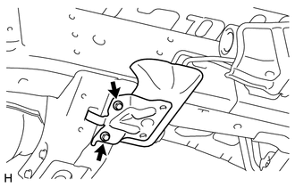
6. REMOVE STABILIZER CONTROL VALVE PROTECTOR
|
(a) Remove the 2 bolts and stabilizer control valve protector. |
|
7. DRAIN SUSPENSION FLUID
|
(a) Loosen the bleeder plug on the stabilizer control with accumulator housing assembly and drain suspension fluid. HINT:
|
|
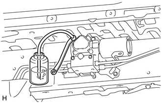
(b) Tighten the bleeder plug.
Torque:
8.3 N·m {85 kgf·cm, 73 in·lbf}
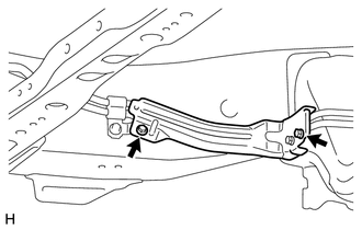
8. REMOVE FRONT STABILIZER TUBE PROTECTOR
|
(a) Remove the 2 bolts and front stabilizer tube protector. |
|
9. REMOVE FRONT STABILIZER CONTROL TUBE INSULATOR
|
(a) Remove the 2 bolts and front stabilizer control tube insulator. |
|
10. REMOVE FRONT STABILIZER CONTROL TUBE
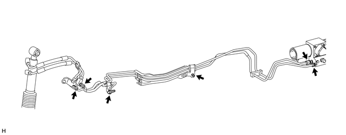
(a) Using a union nut wrench, disconnect the 4 flare nuts.
(b) Remove the 2 bolts and front stabilizer control tubes.
11. REMOVE REAR STABILIZER CONTROL TUBE
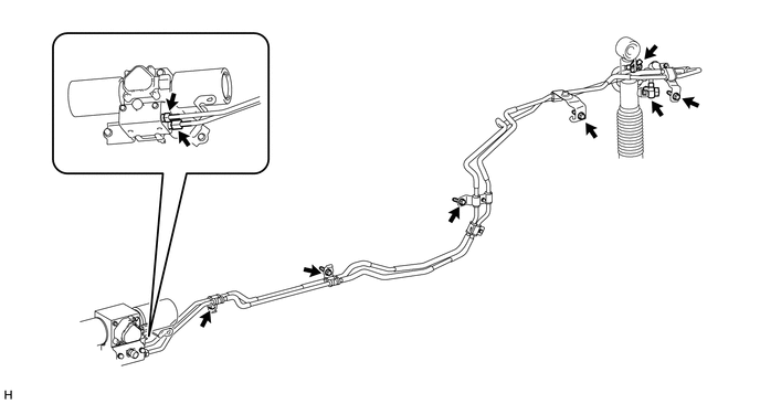
(a) Using a union nut wrench, disconnect the 2 flare nuts.
(b) Remove the 2 union bolts of the rear stabilizer control cylinder and the 2 pressure port gaskets.
(c) Remove the 4 bolts and rear stabilizer control tubes.
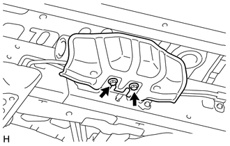
12. REMOVE STABILIZER CONTROL WITH ACCUMULATOR HOUSING ASSEMBLY
|
(a) Disconnect the connector, and then detach the clamp from the sensor bracket. |
|
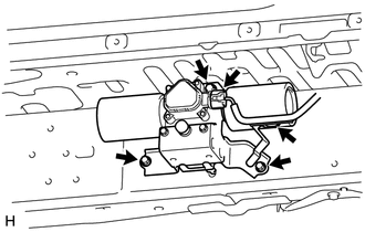
(b) Remove the 3 bolts and stabilizer control with accumulator housing.
NOTICE:
Do not disassemble the stabilizer control with accumulator housing assembly or expose it to an open flame as the accumulator of the stabilizer control with accumulator housing assembly contains gas.
 Installation
INSTALLATION
PROCEDURE
1. INSTALL STABILIZER CONTROL WITH ACCUMULATOR HOUSING ASSEMBLY
(a) Install the stabilizer control with accumulator housing with the 3 bolts.
Torque:
29 N·m {296 kgf·cm, ...
 Disposal
DISPOSAL
PROCEDURE
1. DISPOSE OF STABILIZER CONTROL WITH ACCUMULATOR HOUSING ASSEMBLY
(a) Using a drill, make a hole in the areas of the accumulator housing
indicated in the illustra ...
Other materials about Toyota 4Runner:
Dcm Power Source Circuit
DESCRIPTION
This is the power source circuit to operate the DCM (Telematics Transceiver).
WIRING DIAGRAM
CAUTION / NOTICE / HINT
NOTICE:
Inspect the fuses for circuits related to this system before performing the following
inspection procedure.
PROCE ...
Data List / Active Test
DATA LIST / ACTIVE TEST
1. READ DATA LIST
HINT:
Using the Techstream to read the Data List allows the values or states of switches,
sensors, actuators and other items to be read without removing any parts. This non-intrusive
inspection can be very usefu ...
0.0086