Toyota 4Runner: Removal
REMOVAL
PROCEDURE
1. REMOVE ASSIST STRAP HOLE COVER
.gif)
2. REMOVE ASSIST STRAP ASSEMBLY
3. REMOVE BACK DOOR TRIM PANEL ASSEMBLY
4. REMOVE MULTIPLEX NETWORK DOOR ECU
5. REMOVE NO. 2 BACK DOOR SERVICE HOLE COVER
6. REMOVE BACK DOOR LOCK CYLINDER (w/o Smart Key System)
7. REMOVE BACK DOOR OUTSIDE GARNISH (w/o Smart Key System)
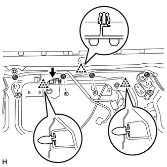
(a) Disconnect the connector.
(b) Remove the 4 nuts.
(c) Detach the 3 clips and remove the back door outside garnish.
8. REMOVE BACK DOOR OUTSIDE GARNISH (w/ Smart Key System)
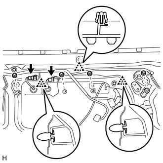
(a) Disconnect the 2 connectors.
(b) Remove the 4 nuts.
(c) Detach the 3 clips and back door outside garnish.
 Components
COMPONENTS
ILLUSTRATION
ILLUSTRATION
...
 Disassembly
DISASSEMBLY
PROCEDURE
1. REMOVE BACK DOOR OPENER SWITCH ASSEMBLY
2. REMOVE NO. 2 BACK DOOR OUTSIDE GARNISH
(a) Detach the 2 clips and No. 2 back door outside garnish.
3. REMOVE LICENSE PLATE ...
Other materials about Toyota 4Runner:
How To Proceed With Troubleshooting
CAUTION / NOTICE / HINT
HINT:
The wireless door lock control system troubleshooting procedures are
based on the premise that the power door lock control system is operating
normally. Check the power door lock control system first before troub ...
Operation Check
OPERATION CHECK
1. CHECK FRONT POWER SEAT FUNCTION
(a) Check the basic functions.
Text in Illustration
*a
Sliding function
*b
Front vertical function
*c
Lifter function
...
0.009