Toyota 4Runner: Removal
REMOVAL
CAUTION / NOTICE / HINT
HINT:
- Use the same procedure for the RH and LH sides.
- The procedure listed below is for the LH side.
PROCEDURE
1. REMOVE ROOF RAIL ASSEMBLY LH (w/ Roof Rack)
(a) Remove the roof rail (See page .gif) ).
).
2. REMOVE FRONT ROOF DRIP SIDE MOULDING COVER LH (w/o Roof Rack)
HINT:
Use the same procedure to remove the front roof drip side moulding cover on the other side.
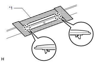
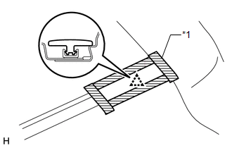
(a) Put protective tape around the front roof drip side moulding cover.
Text in Illustration|
*1 |
Protective Tape |
(b) Detach the 2 claws and remove the front roof drip side moulding cover.
3. REMOVE ROOF RACK BRACKET (w/o Roof Rack)
HINT:
Use the same procedure to remove the roof rack bracket on the other side.
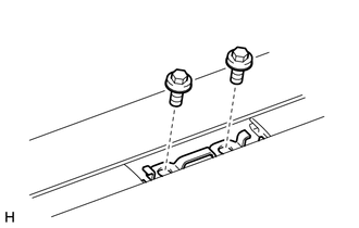
(a) Remove the 2 bolts and roof rack bracket.
4. REMOVE ROOF DRIP SIDE FINISH MOULDING LH
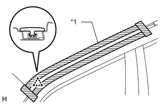
(a) Put protective tape around the roof drip side finish moulding.
Text in Illustration|
*1 |
Protective Tape |
(b) Detach the clip and remove the roof drip side finish moulding.
NOTICE:
- When removing the rear roof drip side finish moulding, be careful not to damage the roof drip side finish moulding clip.
- If the roof drip side finish moulding clip is damaged or becomes detached from the vehicle, replace it with a new one.
5. REMOVE CENTER ROOF DRIP SIDE FINISH MOULDING LH
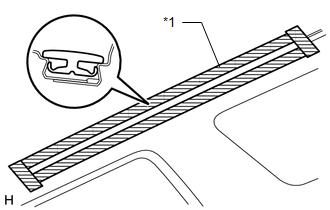
(a) Put protective tape around the center roof drip side finish moulding.
Text in Illustration|
*1 |
Protective Tape |
(b) Remove the center roof drip side finish moulding.
6. REMOVE ROOF DRIP SIDE FINISH MOULDING LH
(a) Put protective tape around the roof drip side finish moulding.
Text in Illustration|
*1 |
Protective Tape |
(b) Detach the clip and remove the roof drip side finish moulding.
NOTICE:
- When removing the roof drip side finish moulding, be careful not to damage the roof drip side finish moulding clip.
- If the roof drip side finish moulding clip is damaged or becomes detached from the vehicle, replace it with a new one.
 Components
COMPONENTS
ILLUSTRATION
...
 Installation
INSTALLATION
CAUTION / NOTICE / HINT
HINT:
Use the same procedure for the RH and LH sides.
The procedure listed below is for the LH side.
When installing the clip, heat the vehicle ...
Other materials about Toyota 4Runner:
Diagnostic Trouble Code Chart
DIAGNOSTIC TROUBLE CODE CHART
HINT:
If a trouble code is output during the DTC check, inspect the trouble areas listed
for that code. For details of the code, refer to the "See page" below.
Sliding Roof System
DTC Code
Det ...
Crawl Control
Allows travel on extremely rough off-road surfaces at a fixed low speed
without pressing the accelerator or brake pedal. Minimizes loss of traction or
vehicle slip when driving on slippery road surfaces, allowing for stable
driving.
Crawl Control switch ...
0.0067